1993 Ford Taurus A/C Lines & Accumulator Exploded Diagram - Part Numbers
Reference · 1992-1995 TaurusAll 9 exploded parts diagrams
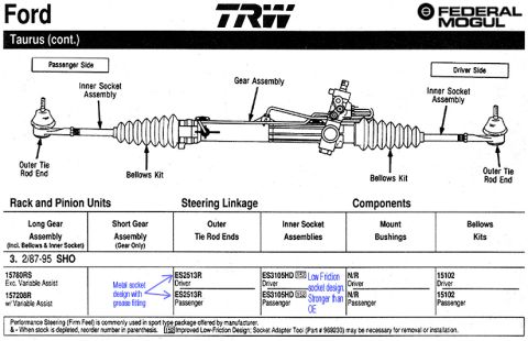


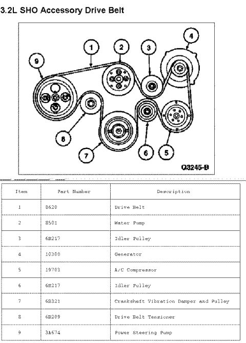
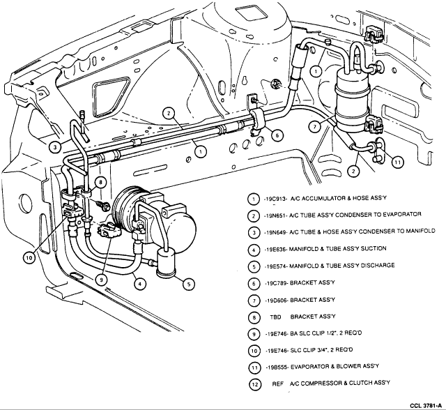
Parts diagram of an air conditioning system showing accumulator, tubes and brackets with numbered part-number callouts.
Part of 1992-1995 Ford Taurus Exploded Parts Diagrams
This is an exploded parts diagram of the air conditioning refrigerant line routing in the engine compartment of a Ford vehicle, uploaded to a 1993 Ford Taurus gallery. The illustration shows the engine bay from the front-left, with the A/C compressor and clutch assembly at lower left, hoses and tubes routed along the firewall and inner fenders, and the accumulator/drier canister at the right side of the engine compartment. Twelve numbered callouts identify each component and its Ford base part number: the A/C accumulator and hose assembly (19C913), condenser-to-evaporator A/C tube assembly (19N651), condenser-to-manifold A/C tube and hose assembly (19N649), suction manifold and tube assembly (19E636), discharge manifold and tube assembly (19E574), two bracket assemblies (19C789 and 19D606) plus a third bracket listed as TBD, 1/2" and 3/4" SLC clips (19E746-BA and 19E746, two required each), the evaporator and blower assembly (19B555), and the A/C compressor and clutch assembly listed as reference only. The drawing carries the reference number CCL 3781-A. The document is useful for identifying A/C line part numbers, mounting bracket and clip locations, and hose routing for repair or replacement work.
Is this accurate? Sign in to help verify it.
Frequently asked questions
- What is the part number for the A/C accumulator and hose assembly?
- Callout 1 identifies the A/C accumulator & hose assembly as base part number 19C913.
- Which part numbers cover the suction and discharge manifold/tube assemblies?
- The suction manifold & tube assembly is 19E636 (callout 4) and the discharge manifold & tube assembly is 19E574 (callout 5).
- How many SLC clips are required and what sizes are they?
- Two 1/2" SLC clips (19E746-BA) and two 3/4" SLC clips (19E746) are required, per callouts 9 and 10.
- What part number is the tube from the condenser to the evaporator?
- Callout 2 lists the A/C tube assembly from condenser to evaporator as 19N651.
- Is the A/C compressor part number given in this diagram?
- No. Callout 12 lists the A/C compressor & clutch assembly as 'REF' (reference only), and the bracket at callout 8 is listed as 'TBD'.

No comments yet.