Home/
Registry/
Ford/
Bronco/
1992-1996/
1993 Ford Bronco/
Photo
supermotors.net/registry/media/574823
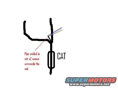
O2 Sensor Location Diagram - Welded Bung Before Catalytic Converter (Ford Bronco)
Reference · 1992-1996 BroncoAll 95 schematics


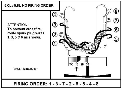
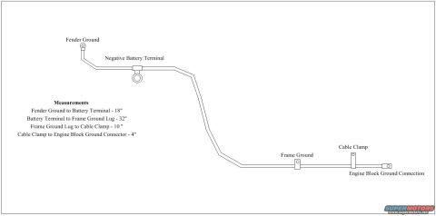
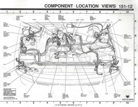
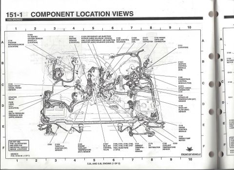









Crude hand-drawn schematic of an exhaust pipe and catalytic converter noting a welded-in O2 sensor location.
Part of 1992-1996 Ford Bronco Schematics
This is a simple hand-drawn schematic (created in a basic paint program) illustrating where to install an oxygen (O2) sensor in a vehicle's exhaust system. The drawing shows thick black lines representing exhaust piping: a downpipe/Y-pipe section at the top joining into a single pipe that leads down to an oval shape labeled "CAT" (catalytic converter), with the exhaust continuing beyond it. A red arrow points to a spot on the exhaust pipe just upstream (above) of the catalytic converter, at or near the junction where the pipes merge. The red annotation reads "Pipe welded in wit o2 sensor screwedin the end," indicating that a bung or short pipe stub is welded into the exhaust at this location, with the O2 sensor threaded into it. Small colored lines (blue, green, purple) near the sensor location appear to represent the O2 sensor's wiring. A reader can learn from this document the intended mounting location for an O2 sensor: welded into the exhaust pipe ahead of the catalytic converter. The document contains no year, make, model, part numbers, torque specs, or wire color codes, it is purely a positional illustration. It was uploaded to a 1993 Ford Bronco gallery, though the drawing itself is generic.
Is this accurate? Sign in to help verify it.
Frequently asked questions
- Where does the diagram show the O2 sensor being installed?
- In a pipe welded into the exhaust just upstream of the catalytic converter (labeled "CAT"), with the O2 sensor screwed into the end of the welded-in pipe.
- How is the O2 sensor attached according to this drawing?
- A pipe (bung/stub) is welded into the exhaust, and the O2 sensor is screwed into the end of that pipe.
- Is the sensor located before or after the catalytic converter in this diagram?
- Before (upstream of) the catalytic converter, near where the exhaust pipes merge.
- Does the diagram give any part numbers or torque specifications?
- No. It is a simple hand-drawn sketch showing only the sensor location; no part numbers, torque values, or wire colors are given.






No comments yet.