1996 Ford F-150/F-250/F-350/Bronco Oil Pressure Gauge & Switch Operation

Reference · 1987-1991 BroncoAll 54 manual pages
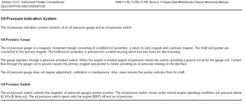

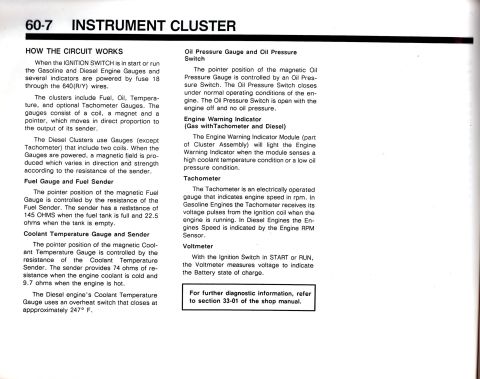
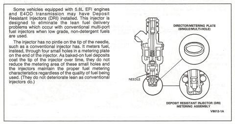
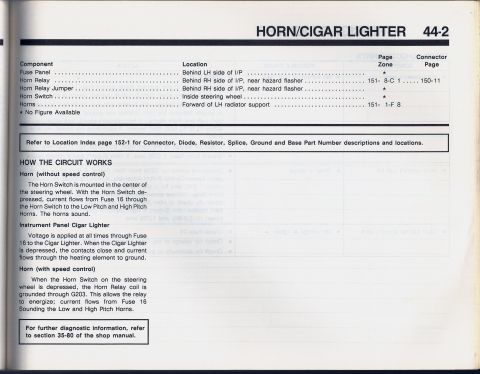
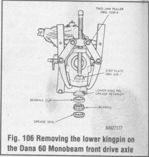




Scanned Ford workshop manual page describing the oil pressure indication system, gauge, and pressure switch operation.
Part of 1987-1991 Ford Bronco Manual Pages
This page is from Section 13-01 (Instrument Cluster, Conventional) of the 1996 Ford F-150, F-250, F-350, Bronco, and F-Super Duty Motorhome Chassis Workshop Manual, in the Description and Operation subsection. It explains the Oil Pressure Indication System, which consists of an oil pressure gauge and an oil pressure switch. The gauge is described as a magnetic movement design with a bobbin/coil assembly, a return-to-zero magnet, and a primary magnet to which the shaft and pointer are attached; the bobbin/coil assembly presses into a metal housing with two dial-mounting holes. Operation is via a pressure-activated switch: when the engine starts, oil pressure closes the switch, grounding the gauge coil circuit, and current flow rotates the primary magnet and pointer to display an oil pressure reading. The document states the gauge requires no adjustment, calibration, or maintenance, and warns never to remove the pointer indicator from its shaft. The oil pressure switch closes under normal operating conditions (oil pressure above 42 kPa / 6 lb/sq in) and opens with the engine (base part 6007) off with no oil pressure. Readers learn how the factory oil pressure gauge and switch function and the pressure threshold at which the switch closes.
This document covers 1996, which may differ from this 1989 Ford Bronco.
Is this accurate? Sign in to help verify it.
Frequently asked questions
- How does the oil pressure gauge work on a 1996 Ford F-150, F-250, F-350, or Bronco?
- It is a magnetic movement gauge operated through a pressure-activated switch. When the engine starts, oil pressure closes the switch, providing a ground circuit for the gauge coil; current flow rotates the primary magnet and pointer to show a reading on the dial face.
- At what pressure does the 1996 Ford oil pressure switch close?
- The oil pressure switch closes under normal engine operating conditions when oil pressure is above 42 kPa (6 lb/sq in). It opens with the engine off and no oil pressure.
- Does the factory oil pressure gauge need calibration or adjustment?
- No. The manual states the oil pressure gauge does not require adjustment, calibration or maintenance, and it warns never to remove the pointer indicator from its shaft.
- What components make up the oil pressure indication system?
- The system consists of an oil pressure gauge and an oil pressure switch. The gauge itself is made of a bobbin/coil assembly, a return-to-zero magnet, and a primary magnet connected to the shaft and pointer.





No comments yet.