SuperMotors SuperMotors SUPERMOTORS Search: try “orange Bronco on 35s”
Home/ Registry/ Ford/ Bronco/ 1987-1991/ “the magic carpet”/ Photo supermotors.net/registry/media/144238

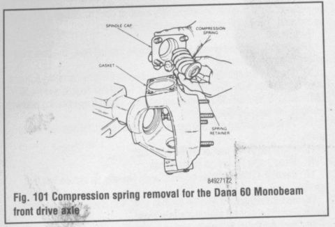
Dana 60 Monobeam Front Axle Compression Spring Removal Diagram (Fig. 101)

Service manual figure 101 showing compression spring removal on Dana 60 Monobeam front axle
Service manual figure 101 showing compression spring removal on Dana 60 Monobeam front axleOriginal file
Service manual figure 101 showing compression spring removal on Dana 60 Monobeam front axle

Reference · 1987-1991 BroncoAll 54 manual pages
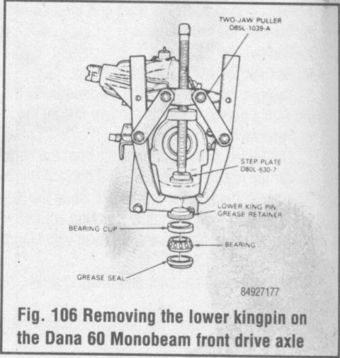
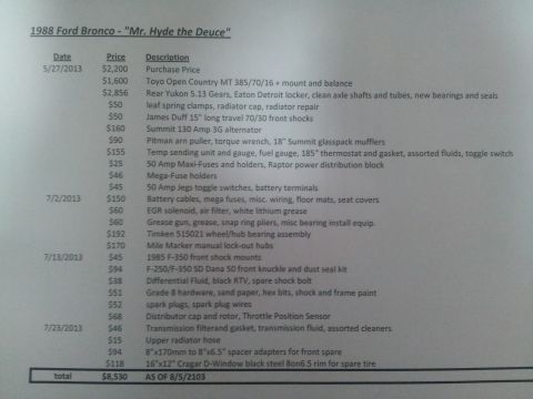
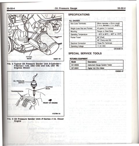
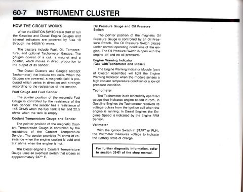
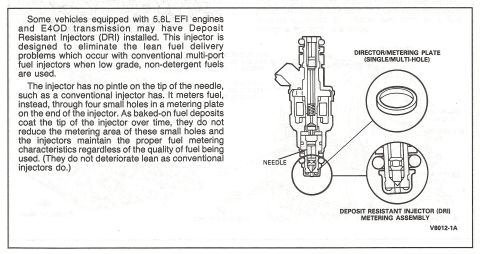
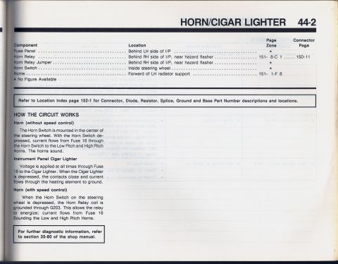
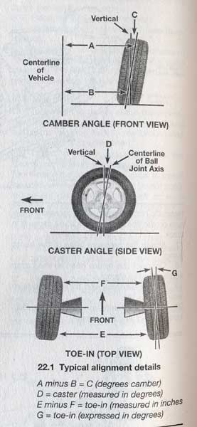
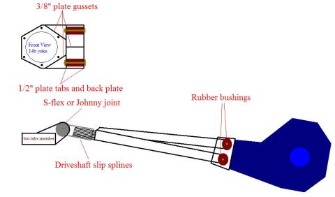
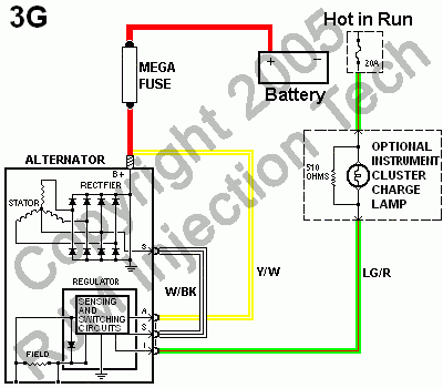
Dana 60 Monobeam Axle Lower Kingpin Removal Diagram - Ford Two-Jaw Puller Dana 60 Monobeam Front Axle Tapered Bushing Removal Diagram - Ford Knuckle Dana 60 Monobeam Front Axle Lower Kingpin Removal Diagram - Fig. 102 Dana 60 Monobeam Front Axle Compression Spring Removal Diagram (Fig. 101) Ford 5.0L/5.8L Air Throttle Body Assembly Diagram - Canister Purge Ports & TPS Ford 5.0L/5.8L EFI Air Throttle Body Assembly Diagram - TPS & Air Bypass Valve 1988 Ford Bronco Build Cost Sheet - "Mr. Hyde the Deuce" Parts & Expense List 1990 Ford Bronco/F-Series Oil Pressure Gauge Specs & Sender Location 33-32-4 1990 Ford Bronco Instrument Cluster Circuit Operation & Sender Specs (60-7) Ford 5.8L EFI Deposit Resistant Injector (DRI) Diagram & Description - E4OD 1990 Ford Bronco Horn & Cigar Lighter Circuit (EVTM 44-2) - Locations & Operation Wheel Alignment Basics Diagram - Camber, Caster & Toe-In Explained (Ford Bronco) 54manual pages1987-1991 Ford Bronco More reference 14-Bolt Axle Anti-Wrap Traction Bar Design Diagram - Ford Bronco Wrap Bar IdeaSchematic Ford 3G Alternator Wiring Diagram - Mega Fuse, Charge Lamp & Wire ColorsWiring diagram Ford Canister Purge Regulator Valve (CANP 9C915) Test Procedure - Figure 11Service procedure Welder Input Data Plate - Serial JH229505, Stock 901782, 200/230/460V SpecsSpec plate Ford 5.0L V8 PCV Valve & Hose Routing Diagram - 9A474, 6B890, 6A664Exploded parts Magnum Metropolitan Brochure - Ford Bronco/F-Series Suburban-Style ConversionBrochure Tubing Adapter Blueprint 2.00" OD x 1.375" ID x 3" - 1.125"-12 TPI RH ThreadBlueprint Ford Thermactor Combination Valve Diagram - Air Bypass/Control Ports LabeledVacuum routing 1990 Ford Bronco Fuse Panel Diagram: Fuse Positions, Amps & Circuits (11-2)Fuse chart Ford V8 Intake Manifold Bolt Tightening Sequence Diagram - Stud LocationsTorque spec

Service manual figure illustrating compression spring removal for the Dana 60 Monobeam front drive axle with labeled parts.

Part of 1987-1991 Ford Bronco Manual Pages

AI caption · Photo 641 of 1850

This document is a single scanned service-manual illustration (Figure 101) showing compression spring removal for the Dana 60 Monobeam front drive axle. The line drawing depicts an exploded view of the axle's steering knuckle/spindle area, with callout labels identifying four components: the spindle cap (a flanged cap with bolt holes), the compression spring (shown between the spindle cap and spring retainer), the gasket (which sits between the spindle cap and the knuckle face), and the spring retainer. The knuckle is shown mounted on the axle housing with wheel studs visible on the hub area. A reference number, 84927172, appears near the caption. The page contains no written procedure, torque specifications, year/model applicability statements, or part numbers other than the illustration reference number. A reader can learn the relative positions and assembly order of the spindle cap, gasket, compression spring, and spring retainer on a Dana 60 Monobeam front drive axle, which is useful when disassembling or reassembling the spindle area during hub, spindle, or axle shaft service.

Is this accurate? Sign in to help verify it.

Frequently asked questions

What does this diagram show?
It is Fig. 101, illustrating compression spring removal for the Dana 60 Monobeam front drive axle.
What parts are labeled in the Dana 60 Monobeam spindle diagram?
The callouts identify the spindle cap, compression spring, gasket, and spring retainer.
Where does the gasket go in this assembly?
The gasket is shown seated on the knuckle face, between the knuckle and the spindle cap.
Is there a reference number on this illustration?
Yes, the number 84927172 appears near the figure caption.

Comments

No comments yet.

More 1987-1991 Broncos