1986 Ford Bronco Steering Column Exploded Diagram - Ignition Lock Cylinder Parts
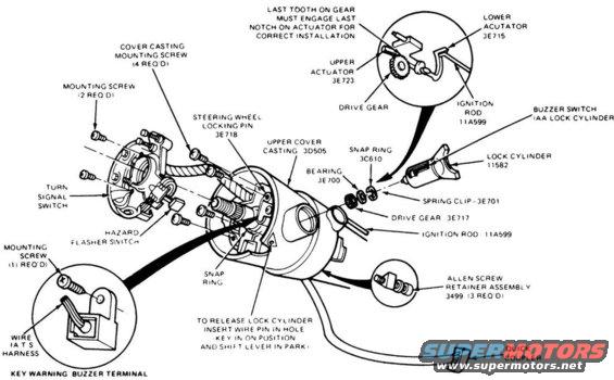
Exploded parts breakdown of a Ford steering column showing the ignition lock cylinder, actuators, drive gear, and turn signal switch components.
This document is an exploded parts diagram of a Ford steering column and ignition lock cylinder assembly. It illustrates the upper cover casting (3D505), steering wheel locking pin (3E718), turn signal switch, hazard flasher switch, key warning buzzer terminal and wire harness, snap rings (3C610), bearing (3E700), spring clip (3E701), drive gear (3E717), upper actuator (3E723), lower actuator (3E715), ignition rod (11A599), lock cylinder (11582), Allen screw retainer assembly (3499, 3 required), and quick coupler. Fastener quantities are noted: 2 mounting screws for one bracket, 4 cover casting mounting screws, 1 mounting screw for the buzzer terminal, and 3 Allen screws in the retainer assembly. Two important service notes are included: an inset detail stating that the last tooth on the drive gear must engage the last notch on the actuator for correct installation, and instructions that to release the lock cylinder, a wire pin must be inserted in the hole with the key in the ON position and the shift lever in Park. This diagram is useful for anyone disassembling or reassembling a Ford tilt/steering column, replacing an ignition lock cylinder, or repairing the turn signal, hazard, or key warning buzzer switches, as it identifies part relationships and Ford base part numbers.
Is this accurate? Sign in to help verify it.
Frequently asked questions
- How do you release the lock cylinder on this Ford steering column?
- Per the diagram note: insert a wire pin in the hole with the key in the ON position and the shift lever in Park.
- What is the Ford part number for the ignition lock cylinder?
- The lock cylinder is shown as part number 11582; the associated ignition rod is 11A599.
- What is the correct alignment for the drive gear and actuator?
- The last tooth on the gear must engage the last notch on the actuator for correct installation.
- How many screws hold the upper cover casting on?
- The cover casting mounting screws are labeled '4 REQ'D' (four required).
- What part numbers are given for the column internals?
- Steering wheel locking pin 3E718, upper cover casting 3D505, upper actuator 3E723, lower actuator 3E715, snap ring 3C610, bearing 3E700, spring clip 3E701, drive gear 3E717, ignition rod 11A599, lock cylinder 11582, and Allen screw retainer assembly 3499.
Comments
More from this build






No comments yet.