Dual Horn Wiring Diagram - Air Horns & Stock Horns with Relays & SPDT Switch
Reference · 1980-1986 BroncoAll 92 wiring diagrams
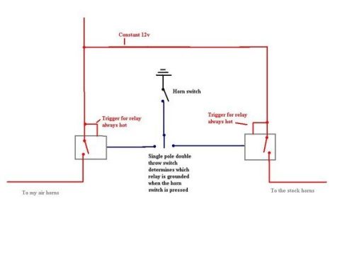







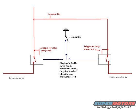
Wiring diagram with two relays and an SPDT horn switch selecting air or stock horns from constant 12V.
Part of 1980-1986 Ford Bronco Wiring Diagrams
This is a hand-drawn wiring diagram (created in a basic drawing program) showing how to wire dual horn systems, aftermarket air horns and factory stock horns, on one vehicle using two relays and a selector switch. A constant 12V feed (drawn in red) supplies both relay triggers, each labeled 'Trigger for relay always hot,' as well as the load circuits. The factory horn switch provides a ground path, and a single pole double throw (SPDT) switch placed between the horn switch and the two relays determines which relay coil is grounded when the horn button is pressed. Depending on the SPDT switch position, either the relay feeding 'my air horns' (left side) or the relay feeding 'the stock horns' (right side) is energized. The diagram uses red lines for constant 12V power and dark blue lines for the switched ground/trigger circuit. No fuse ratings, wire gauges, wire colors codes, part numbers, or relay pin numbers are given; it is a conceptual schematic rather than a factory diagram. It was uploaded to a 1986 Ford Bronco gallery alongside related horn, hub, and steering column documents, and is useful for anyone wanting to toggle between air horns and stock horns using the original horn button.
Is this accurate? Sign in to help verify it.
Frequently asked questions
- How does this diagram switch between air horns and stock horns?
- A single pole double throw (SPDT) switch determines which of the two relays is grounded when the horn switch is pressed, so pressing the horn button activates either the air horns or the stock horns depending on the switch position.
- How are the relays powered in this setup?
- Both relay triggers are fed by a constant 12V supply and are labeled 'Trigger for relay always hot.' The horn switch completes the ground side through the SPDT selector switch.
- What role does the factory horn switch play?
- The horn switch is on the ground side of the circuit; when pressed, it grounds whichever relay the SPDT switch is set to, energizing that relay to sound the corresponding horns.
- Does the diagram specify fuse sizes or wire gauges?
- No. The diagram only shows the circuit layout with a constant 12V feed, two relays, a horn switch, and an SPDT switch; no fuse ratings, wire gauges, or part numbers are listed.






No comments yet.