Ford 5-Screw Automatic Hub Lock Exploded Diagram - Parts & Assembly Order
Reference · 1980-1986 BroncoAll 61 exploded parts diagrams
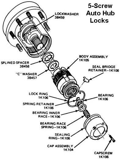
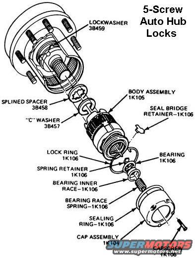
Exploded parts diagram of a 5-screw automatic locking hub showing body assembly, bearings, lock ring and seals with part numbers.
Part of 1980-1986 Ford Bronco Exploded Parts Diagrams
This document is an exploded parts diagram titled "5-Screw Auto Hub Locks," showing the disassembled component stack of an automatic locking hub assembly. The illustration depicts the wheel hub with wheel studs at the top, followed by the internal hub lock components in exploded order: a lockwasher (part 3B459), splined spacer (3B458), "C" washer (3B457), body assembly (1K105), seal bridge retainer (1K106), lock ring (1K106), spring retainer (1K106), bearing (1K106), bearing inner race (1K106), bearing race spring (1K106), sealing ring (1K106), cap assembly (1K104), and capscrew (1K106). From this diagram a reader can learn the correct assembly order of the automatic hub lock components, the Ford base part number group for each piece, and how the cap assembly with its five capscrews attaches to the hub body. Many of the small internal pieces share the 1K106 base number, indicating they are serviced under that part group. The document was uploaded to a 1986 Ford Bronco gallery alongside horn and steering column diagrams, and while no year, make, or model is printed on the diagram itself, the part numbering style is consistent with Ford service literature. No torque specifications or instructions are included, this is purely a component identification/exploded view.
Is this accurate? Sign in to help verify it.
Frequently asked questions
- What is the part number for the automatic hub lock body assembly?
- The body assembly is labeled with part number 1K105 in the diagram.
- What part number is the cap assembly on 5-screw auto hub locks?
- The cap assembly is labeled 1K104, and it is retained by capscrews labeled 1K106.
- In what order do the washers and spacer install on the hub?
- Per the exploded view, the lockwasher (3B459) is at the hub, followed by the splined spacer (3B458) and then the "C" washer (3B457) before the body assembly (1K105).
- Which internal hub lock parts share the 1K106 part number?
- The seal bridge retainer, lock ring, spring retainer, bearing, bearing inner race, bearing race spring, sealing ring, and capscrew are all labeled 1K106.
- How many screws hold the hub lock cap on?
- The title identifies these as 5-screw auto hub locks, so the cap assembly is retained by five capscrews.
No comments yet.