Home/
Registry/
Ford/
Bronco/
1980-1986/
“Big Freak'N Machine”/
Photo
supermotors.net/registry/media/621610
Exploded Parts Diagram - Cylindrical Suppressor Tube Assembly (No Text/Dimensions)
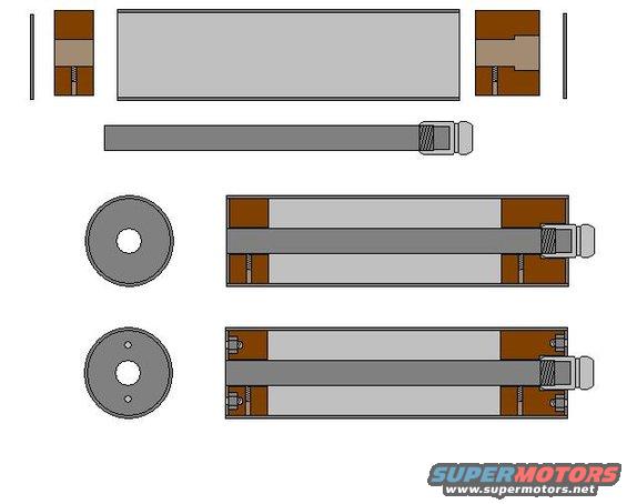
Cross-section parts diagram showing bushings, shaft, washers, and bolts arranged as an assembly breakdown.
Part of 1980-1986 Ford Bronco Exploded Parts Diagrams
This document is a text-free, CAD-style exploded parts illustration uploaded to SuperMotors.net under the filename "Joce's supressor.JPG" and associated with a 1985 Ford Bronco. It shows the construction of a cylindrical device, apparently a homemade suppressor or damper/resonator-type assembly. The top row presents an exploded view: two brown end plugs (shown in cross-section with threaded fasteners), a long gray outer tube, and thin retaining plates or washers at each end. Below that is a long gray central rod or shaft with a threaded/knurled fitting and a connector piece at one end. Two circular face views show the end caps: one with a single central hole and one with a central hole plus two smaller offset holes (likely for fasteners or vents). Two assembled longitudinal cross-sections show the rod installed through the tube with the end caps and screws in place, illustrating internal chamber spaces on either side of the rod. Because the drawing contains no dimensions, materials callouts, part numbers, or written instructions, a reader can only learn the general arrangement and assembly sequence of the components, not specific sizes, thread specs, or vehicle applicability.
Is this accurate? Sign in to help verify it.
Frequently asked questions
- What does this diagram show?
- It is an exploded and cross-sectional illustration of a cylindrical tube assembly with two end caps/plugs, a central rod with a threaded end fitting, and fasteners, no written labels or dimensions are included.
- Are there any part numbers or measurements in this document?
- No. The drawing contains no text at all, no part numbers, dimensions, torque values, or material callouts.
- How do the components fit together?
- The assembled cross-section views show the central rod passing lengthwise through the outer tube, with a brown plug and a screw securing each end, and the threaded fitting/connector protruding from one end.
- What do the two circular views represent?
- They appear to be face views of the end caps: one has a single central hole, and the other has a central hole plus two smaller offset holes.
Comments
More from this build







No comments yet.