Home/
Registry/
Ford/
Bronco/
1980-1986/
1986 Ford Bronco/
Photo
supermotors.net/registry/media/768340
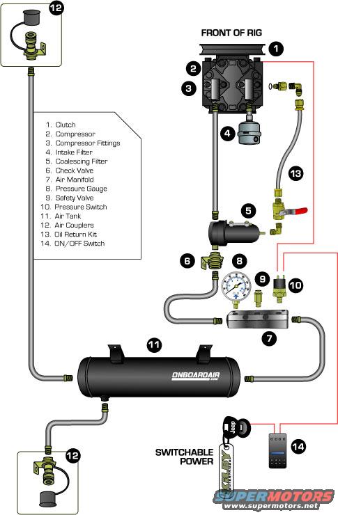
Kilby OnBoardAir Compressor System Schematic - Parts Diagram & Plumbing Layout
Reference · 1980-1986 BroncoAll 61 exploded parts diagrams


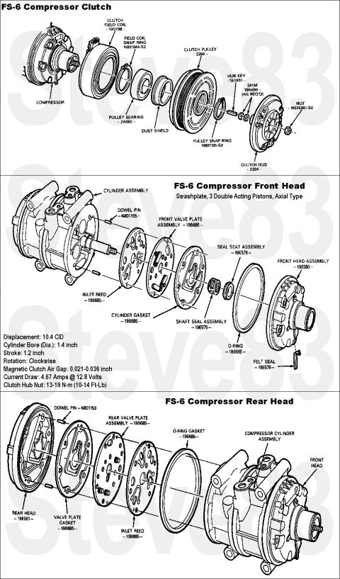
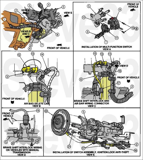
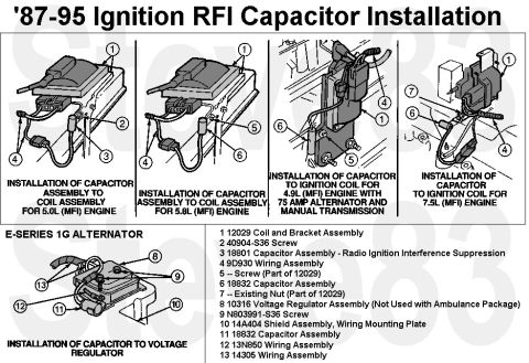
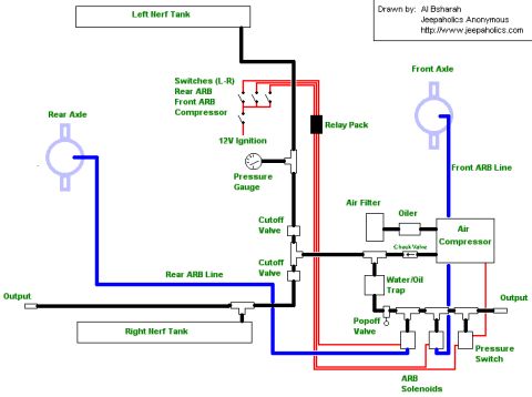






Onboard air compressor system assembly diagram showing compressor, tank, valves, and gauge with a numbered parts legend.
Part of 1980-1986 Ford Bronco Exploded Parts Diagrams
This document is an exploded parts / plumbing schematic for a Kilby Enterprises On Board Air (OBA) system, as promoted at ONBOARDAIR.com. The diagram shows a belt-driven A/C-style compressor (with clutch and pulley oriented toward the 'FRONT OF RIG') converted for use as an air compressor. A numbered legend identifies fourteen components: (1) clutch, (2) compressor, (3) compressor fittings, (4) intake filter, (5) coalescing filter, (6) check valve, (7) air manifold, (8) pressure gauge, (9) safety valve, (10) pressure switch, (11) air tank, (12) air couplers, (13) oil return kit, and (14) ON/OFF switch. Gray lines depict the air plumbing: from the compressor discharge through the coalescing filter and check valve to the air manifold, which carries the pressure gauge, safety valve, and pressure switch, then to the air tank; air couplers are shown at two remote quick-connect points. Red lines depict the electrical wiring from switchable power through the ON/OFF rocker switch to the compressor clutch, with the pressure switch in the circuit. An oil return kit routes from a fitting near the compressor back to the suction side. A reader learns the component names, their relative locations, and how the air and electrical circuits interconnect in this on-board air installation.
Is this accurate? Sign in to help verify it.
Frequently asked questions
- What components are included in this on-board air system schematic?
- The legend lists 14 parts: clutch, compressor, compressor fittings, intake filter, coalescing filter, check valve, air manifold, pressure gauge, safety valve, pressure switch, air tank, air couplers, oil return kit, and ON/OFF switch.
- Where do the pressure gauge, safety valve, and pressure switch mount?
- The diagram shows the pressure gauge (8), safety valve (9), and pressure switch (10) all mounted on the air manifold (7), which sits between the check valve and the air tank.
- How is the compressor powered on and off?
- The red electrical wiring runs from 'SWITCHABLE POWER' through an ON/OFF switch (item 14) to the compressor clutch, with the pressure switch (10) in the circuit.
- How many air coupler locations are shown?
- Two air coupler assemblies (item 12) are shown, one plumbed off the line near the compressor at the top of the diagram and one off the air tank at the bottom.
- What is the oil return kit in the diagram?
- Item 13 is the oil return kit, shown as a line with fittings and a valve routing from the discharge/filter side of the system back to the compressor.






No comments yet.