1993 Ford Probe Power Door Lock Wiring Diagram - Relay, Motors & Switches
Reference · 1993-1997 ProbeAll 65 wiring diagrams
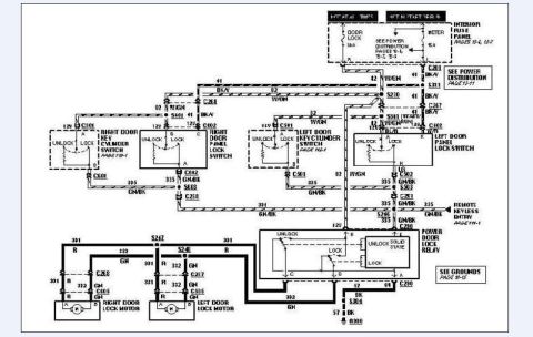
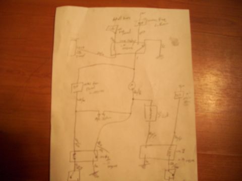









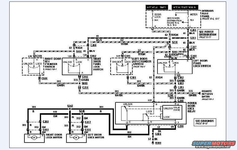
Wiring diagram for power door lock system showing door lock switches, lock motors, relay and color-coded circuits.
Part of 1993-1997 Ford Probe Wiring Diagrams
This document is a scanned power door lock system wiring diagram, uploaded to a 1993 Ford Probe gallery. It shows the complete power door lock circuit: power feeds from the interior fuse panel (a 30A DOOR LOCK fuse hot at all times and a 15A METER fuse hot in start/run), routed through connector C201 with references to power distribution pages 13-5 through 13-11. The diagram traces circuit 41 (BK/Y), circuit 82 (W/GN), circuit 12 (W/GN), and circuit 335 (GN/BK) through the right and left door key cylinder switches (pages 118-1 and 112-1), the right and left door panel lock switches, and splices S230, S311, S601, S603, S246, S247, and S248. Circuit 335 also feeds the remote keyless entry system (page 111-1). A solid-state power door lock relay controls the right and left door lock motors via circuits 301 (R), 312 (GN), and 322 (GN), through connectors C268/C605 (right) and C267/C505 (left). The relay grounds via circuit 57 (BK) through S304 to ground G300 (see grounds page 10-15). Readers can identify wire colors, circuit numbers, connector IDs, and fuse ratings needed to diagnose door lock or keyless entry faults.
Is this accurate? Sign in to help verify it.
Frequently asked questions
- What fuse powers the door locks in this diagram?
- A 30A DOOR LOCK fuse (hot at all times) in the interior fuse panel, plus a 15A METER fuse hot in start or run; see fuse panel pages 13-6 and 13-7.
- What wire color and circuit feed the door lock motors?
- The lock motors are driven by circuit 301 (R, red) and circuits 312/322 (GN, green) from the solid-state power door lock relay, through connectors C268/C605 (right motor) and C267/C505 (left motor).
- Where does the power door lock relay get its ground?
- Through circuit 57 (BK) via connector C210 and splice S304 to ground G300; see grounds page 10-15.
- What circuit connects the door lock system to the remote keyless entry module?
- Circuit 335 (GN/BK), which runs through splice S246 to the remote keyless entry system shown on page 111-1.
- Which connectors serve the right and left door panel lock switches?
- The right door panel lock switch uses connector C602 (with splice S601 on circuit 41 BK/Y), and the left door panel lock switch connects via C502 on circuit 335 GN/BK.






No comments yet.