Kyotto KD20C10AX Solid State Relay Meth Pump Wiring - PNP Pulse Inverter Sketch
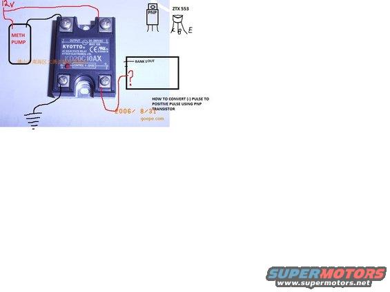
Annotated photo showing how to wire a methanol pump through a solid-state relay using a PNP transistor.
This document is an annotated photograph serving as a hand-drawn wiring diagram for controlling a methanol (meth) injection pump using a solid state relay. The central component is a KYOTTO KD20C10AX AC solid state relay made by Kytech Electronics, Ltd., rated for 24-280VAC output at MAX 10A with a 4-32VDC control input (UL file E206919, CE marked). Hand-drawn wiring shows a 12V supply feeding one output terminal, the METH PUMP connected between 12V and the relay's other output terminal, and a black wire from the relay to chassis ground. On the control side, a red wire runs from the relay's control terminal toward a box labeled 'BANK 1 OUT' with a question mark, indicating uncertainty about how to trigger the relay from a negative-switched output. A sketched PNP transistor (ZTX 553) with pinout markings (C, B, E) is shown alongside the note 'HOW TO CONVERT (-) PULSE TO POSITIVE PULSE USING PNP TRANSISTOR,' suggesting the poster is asking how to invert a negative trigger pulse (e.g., from an ECU bank output) into a positive control signal for the SSR. The image carries a 2006/8/31 date stamp and a goepe.com watermark with Chinese seller text. No vehicle year, make, or model is stated in the document.
Is this accurate? Sign in to help verify it.
Frequently asked questions
- What relay is shown for the meth pump control?
- A KYOTTO KD20C10AX AC solid state relay by Kytech Electronics, Ltd., rated 24~280VAC output, MAX 10A, with a 4~32VDC control input.
- How is the meth pump wired to the relay?
- The meth pump is connected between a 12V supply and one of the relay's output terminals; the other side of the relay circuit goes to ground via a black wire.
- What transistor is suggested for inverting the trigger signal?
- A ZTX 553 PNP transistor is sketched (with C, B, E pins) with the note 'HOW TO CONVERT (-) PULSE TO POSITIVE PULSE USING PNP TRANSISTOR.'
- What triggers the relay's control side in this diagram?
- A red wire runs from the relay control terminal toward a box labeled 'BANK 1 OUT' with a question mark, indicating the trigger source is a bank output whose connection method is in question.
- What is the control voltage range of the KD20C10AX relay?
- The label shows CONTROL 4~32VDC.
Comments
More from this build









No comments yet.