MegaSquirt Pressure Sender Wiring Diagram - Add Autometer Gauge Input to MS

Reference · 1993-1997 ProbeAll 65 wiring diagrams
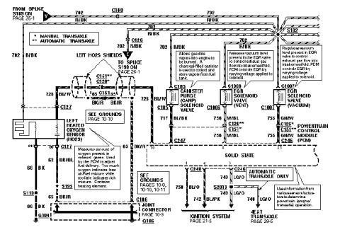
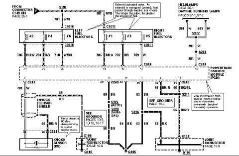
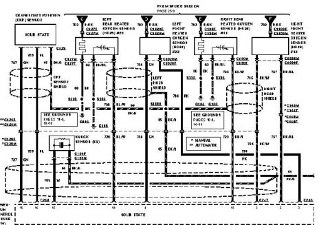
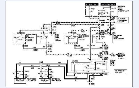
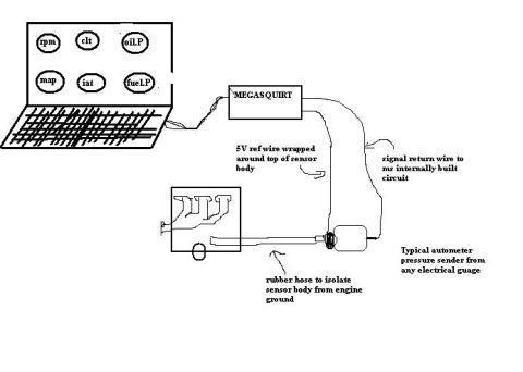









Hand-drawn connection diagram wiring a Megasquirt ECU to an Autometer pressure sender with isolated sensor body.
Part of 1993-1997 Ford Probe Wiring Diagrams
This is a hand-drawn wiring diagram showing how to add an electrical pressure gauge (oil or fuel pressure sender) to a MegaSquirt (MS) engine management system so its reading can be displayed on tuning software. The drawing depicts a laptop displaying six virtual gauges, rpm, clt (coolant temp), oil.P (oil pressure), map, iat (intake air temp), and fuel.P (fuel pressure), connected to a box labeled MEGASQUIRT. From the MegaSquirt, two wires run to a 'typical autometer pressure sender from any electrical guage' mounted off the engine. The callouts explain the hookup: a 5V reference wire is wrapped around the top of the sensor body, a signal return wire runs to the MegaSquirt's internally built circuit, and a length of rubber hose is used to isolate the sensor body from engine ground (so the sender is not grounded through the block). A sketch of an intake manifold/engine shows where the sender connects via the isolating rubber hose. The document teaches a reader the basic wiring and grounding-isolation technique for feeding a single-wire aftermarket pressure sender into a MegaSquirt input for datalogging or gauge display.
Is this accurate? Sign in to help verify it.
Frequently asked questions
- How is the pressure sender connected to the MegaSquirt in this diagram?
- A 5V reference wire is wrapped around the top of the sensor body, and a signal return wire runs to the MegaSquirt's internally built circuit.
- How is the sensor isolated from engine ground?
- A rubber hose is used between the engine and the sender to isolate the sensor body from engine ground.
- What kind of pressure sender does the diagram call for?
- A 'typical autometer pressure sender from any electrical guage.'
- What gauge readouts are shown on the laptop connected to the MegaSquirt?
- rpm, clt, oil.P, map, iat, and fuel.P.






No comments yet.