Ford Probe Oxygen Sensor, CKP & Knock Sensor Wiring Diagram - PCM Circuits
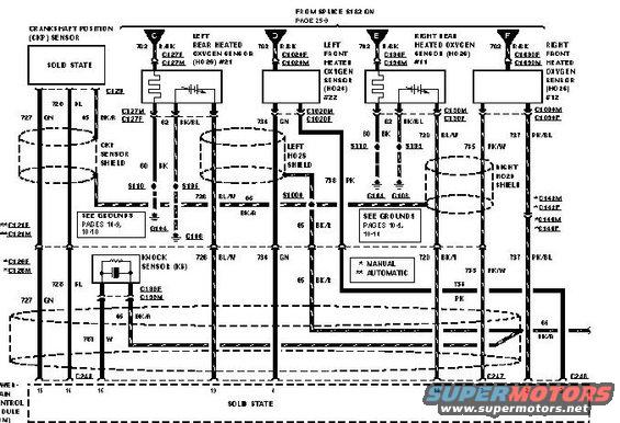
Wiring diagram showing crankshaft position sensor, heated oxygen sensors and knock sensor circuits with color-coded wires.
This document is a factory-style engine management wiring diagram showing the connections between the powertrain control module (PCM, labeled 'SOLID STATE' at the bottom, with the left-margin label cut off but reading '...WERTRAIN CONTROL MODULE') and several engine sensors. It covers the Crankshaft Position (CKP) Sensor, the Knock Sensor (KS), and four heated oxygen sensors: Left Rear HO2S #21, Left Front HO2S #22, Right Rear HO2S #11, and Right Front HO2S #12. Power to the oxygen sensor heaters comes from splice S122 (referenced on page 25-9) via circuit 702 R/BK through connectors C, D, E, and F. The diagram documents circuit numbers and wire colors (e.g., 727 GN, 726 BL, 65 BK, 738 BL/W, 734 GN, 735 PK/W, 737 PK/BL, 761 W), connector identifiers (C129, C127M/C127F, C1020M/C1020F, C130M/C130F, C1030M/C1030F, C138F/C138M, C244, C247, C248), shield drains for the CKP and left/right HO2S wiring, ground splices S110 and S101 with ground points G104 and G108, and cross-references to grounds pages 14-9, 10-10 and 10-14. Footnote symbols distinguish manual (*) versus automatic (**) transmission connector variations (C142M/F, C144M/F, C120F/M, C121F/M). PCM pin numbers (15, 14, 16, 13, 18, 2, 3, others illegible) appear along the bottom.
Is this accurate? Sign in to help verify it.
Frequently asked questions
- How many heated oxygen sensors does this wiring diagram show?
- Four: Left Rear HO2S #21, Left Front HO2S #22, Right Rear HO2S #11, and Right Front HO2S #12, each fed by circuit 702 R/BK from splice S122 (page 25-9).
- What wire color feeds power to the oxygen sensor heaters?
- Circuit 702, a red/black (R/BK) wire, coming from splice S122 shown on page 25-9, through connectors C, D, E, and F.
- What are the wire colors for the crankshaft position (CKP) sensor?
- The CKP sensor circuits shown are 727 GN (green) and 726 BL (blue), with a 65 BK ground and a CKP sensor shield drain, through connector C129.
- What connector is used for the knock sensor?
- The knock sensor (KS) connects through connectors C138F/C138M, with circuits including 727 GN, 726 BL, 65 BK/R, and 761 W.
- Do manual and automatic transmissions use different connectors in this diagram?
- Yes. Footnotes mark * MANUAL and ** AUTOMATIC variations: manual uses C142M/C142F and C120F/C120M, while automatic uses C144M/C144F and C121F/C121M.
Comments
More from this build






No comments yet.