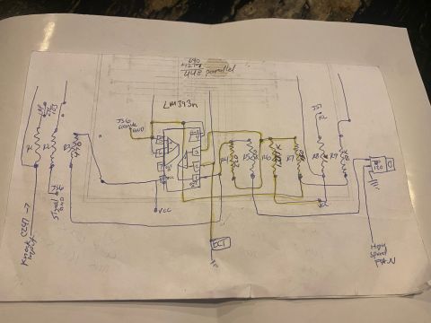
Hand-Drawn Wiring Diagram Sketch - Horn/Pump Relay Circuit (Ford Probe Gallery)
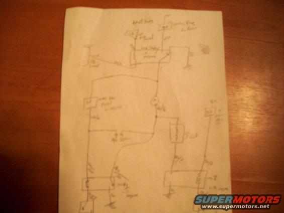
rough hand-drawn wiring diagram on paper showing components, relays and connecting lines for an automotive electrical circuit.
This image is a photograph of a hand-drawn wiring diagram sketched in pen on a sheet of white paper, resting on a wooden table. The photo is significantly out of focus, making nearly all handwritten labels unreadable. The sketch depicts an electrical circuit with multiple components: what appear to be relays (rectangular boxes with internal contacts), a component labeled roughly 'Add'l horns' (additional horns), a pump-related component at top right, several ground symbols, a circular symbol that may represent a lamp or motor, and a resistor/coil element on the right side. Numerous wires interconnect the components, with fraction-style handwritten notations along the wires that likely indicate wire gauge or color codes, though none are legible. The drawing appears to be a homemade schematic — possibly for adding horns, a pump, or auxiliary relays to a vehicle — uploaded to a 1993 Ford Probe gallery among many factory diagram scans for 1993–1996 Probe and 2000 Mazda 626 systems. Because of the blur, the document provides visual circuit topology only; specific wire colors, fuse ratings, pin assignments, and component identities cannot be extracted from this scan.
Is this accurate? Sign in to help verify it.
Frequently asked questions
- What kind of document is this?
- It is a hand-drawn wiring diagram sketched in pen on paper, photographed rather than scanned, showing an electrical circuit with relays, grounds, and interconnecting wires.
- What components can be identified in the diagram?
- A label reading roughly 'Add'l horns' (additional horns) is visible at top, along with what appears to be a pump and relay at top right, several relay-style boxes, ground symbols, a circular lamp/motor symbol, and a resistor or coil element.
- Are wire colors or fuse ratings readable in this diagram?
- No. Fraction-style wire notations are drawn along the wires, but the photo is too blurry to read any wire color codes, gauges, or ratings.
- Does the document state what vehicle it applies to?
- No. The sketch contains no visible year, make, or model information; its vehicle applicability comes only from the uploader's gallery attribution.
Comments
More from this build




No comments yet.