1993 Ford Probe Door Popper Wiring Diagram - Keyless Entry Relay Setup (MAC1)
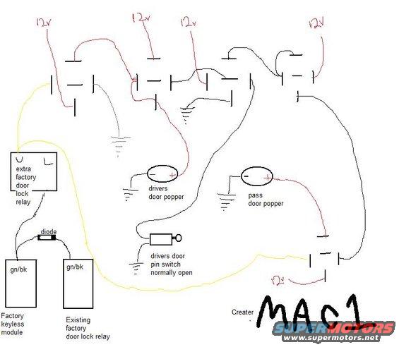
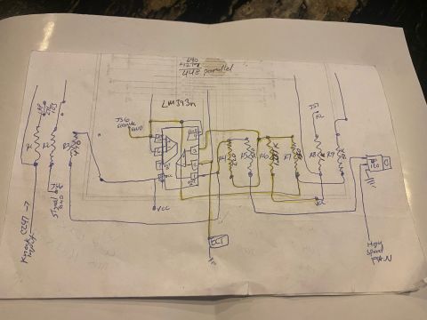
Hand-drawn wiring diagram for door popper solenoids, factory door lock relay, keyless module and 12V circuits.
This is a hand-drawn (computer-sketched) wiring diagram, credited to "MAC1," showing how to wire aftermarket door poppers (solenoids that pop the doors open) into a vehicle's factory keyless entry and door lock system, uploaded to a 1993 Ford Probe gallery. The diagram shows five or more relays fed by 12v sources (marked in red), a driver's door popper and passenger door popper (each drawn as an oval with + and − terminals, the negative side grounded and the positive side switched through relays), and a normally-open driver's door pin switch tied to ground that triggers part of the circuit. On the control side, the factory keyless module and the existing factory door lock relay connect via gn/bk (green/black) wires, with a diode between them, to an added "extra factory door lock relay" that in turn triggers the popper relays (yellow trigger wire routing shown). A reader can learn the general relay-isolation scheme for adding door poppers triggered by the factory keyless entry: tap the gn/bk lock wires through a diode and extra relay, then use multiple 12v-fed relays to fire the popper solenoids, with a door pin switch in the driver's door circuit. No fuse ratings, relay pin numbers, or part numbers are given.
Is this accurate? Sign in to help verify it.
Frequently asked questions
- What wire color connects the factory keyless module to the existing factory door lock relay?
- Both the factory keyless module and the existing factory door lock relay are labeled with gn/bk (green/black) wires, connected through a diode.
- How are the door poppers grounded in this diagram?
- Each popper (drivers door popper and pass door popper) has its negative (−) terminal wired directly to a chassis ground symbol; the positive (+) terminal is fed 12v through relays.
- What type of door pin switch is used?
- The drivers door pin switch is labeled 'normally open' and is wired to ground on one side.
- How many 12v power feeds are shown?
- Five points are marked '12v' in red, four across the top feeding the relays and one at the bottom right feeding another relay.
- What extra components are needed besides the poppers?
- The diagram shows an extra factory door lock relay, a diode in the gn/bk trigger line, several additional relays with 12v feeds, and a normally-open driver's door pin switch.
Comments
More from this build









No comments yet.