Ford Probe Fuel Pump Relay & Inertia Switch Wiring Diagram - PCM/DLC Circuit
Reference · 1993-1997 ProbeAll 65 wiring diagrams
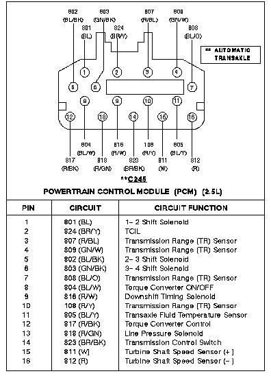
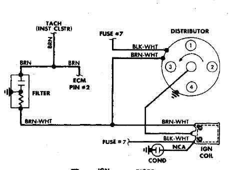
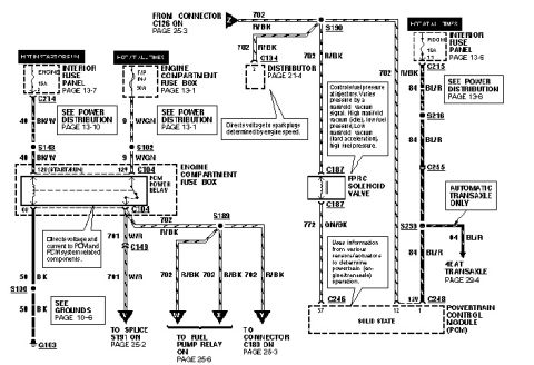
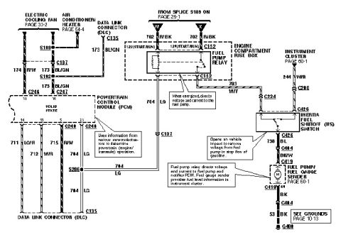
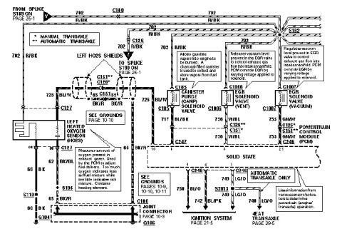
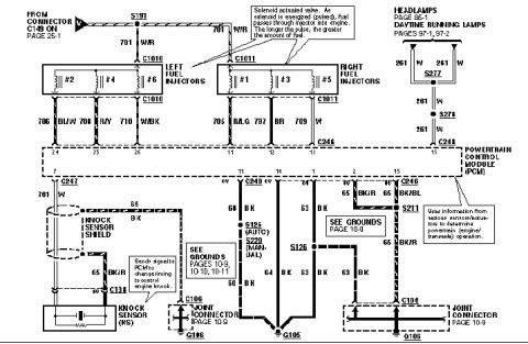
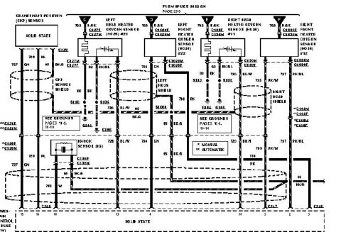









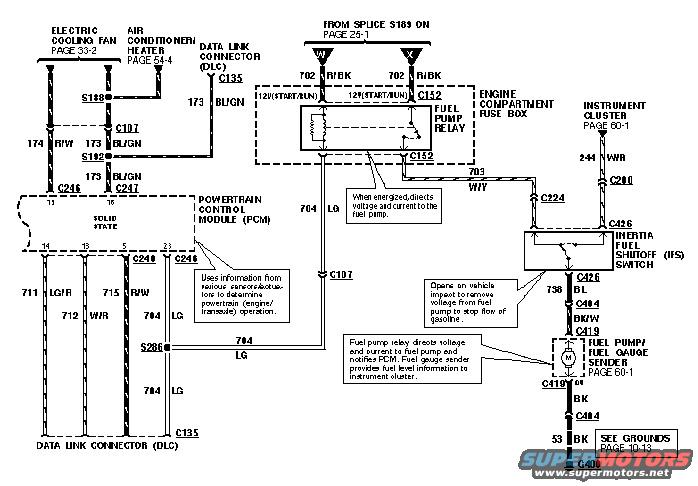
Wiring diagram showing fuel pump relay, inertia fuel shutoff switch, fuel gauge sender and PCM circuits.
Part of 1993-1997 Ford Probe Wiring Diagrams
This document is a factory-style wiring diagram covering the fuel pump and fuel gauge sender circuit for a Ford Probe, along with related Powertrain Control Module (PCM) and Data Link Connector (DLC) wiring. It shows battery/start-run voltage arriving from splice S189 (page 25-1) via circuit 702 R/BK into the engine compartment fuse box, where the fuel pump relay is located. When energized, the relay directs voltage and current through circuit 703 W/Y to the inertia fuel shutoff (IFS) switch, which opens on vehicle impact to cut power to the pump. From the IFS switch, circuit 738 BL and BK/W wiring feed the fuel pump/fuel gauge sender (page 60-1), which grounds through circuit 53 BK at G400 (grounds on page 10-13). The fuel gauge sender provides fuel level information to the instrument cluster via circuit 244 W/R and connector C200. The PCM connects to the DLC (C135) through circuits 711 LG/R, 712 W/R, 715 R/W, and 704 LG, and monitors the fuel pump circuit via 704 LG. Connectors shown include C107, C135, C152, C200, C224, C240, C246, C247, C404, C419, and C426, plus splices S188, S192, and S286. References to electric cooling fan (page 33-2) and A/C-heater (page 54-4) circuits are also noted.
Is this accurate? Sign in to help verify it.
Frequently asked questions
- What wire color and circuit number feed the fuel pump relay?
- Circuit 702 R/BK (red/black) comes from splice S189 (page 25-1) into the engine compartment fuse box to the fuel pump relay, hot in START/RUN (circuit 120).
- What does the inertia fuel shutoff (IFS) switch do?
- It opens on vehicle impact to remove voltage from the fuel pump and stop the flow of gasoline. It receives power on circuit 703 W/Y and outputs on circuit 738 BL.
- How does the fuel gauge get its signal?
- The fuel gauge sender provides fuel level information to the instrument cluster on circuit 244 W/R through connector C200 (instrument cluster, page 60-1).
- Where does the fuel pump ground?
- The fuel pump/fuel gauge sender grounds through BK wiring via connectors C419 and C404 on circuit 53 BK to ground G400 (see grounds page 10-13).
- Which circuits connect the PCM to the Data Link Connector (DLC)?
- Circuits 711 LG/R, 712 W/R, 715 R/W, and 704 LG run between the Powertrain Control Module and the Data Link Connector C135, with 704 LG passing through splice S286.






No comments yet.