Home/
Registry/
Ford/
Bronco/
1980-1986/
“Still Pending”/
Photo
supermotors.net/registry/media/823583
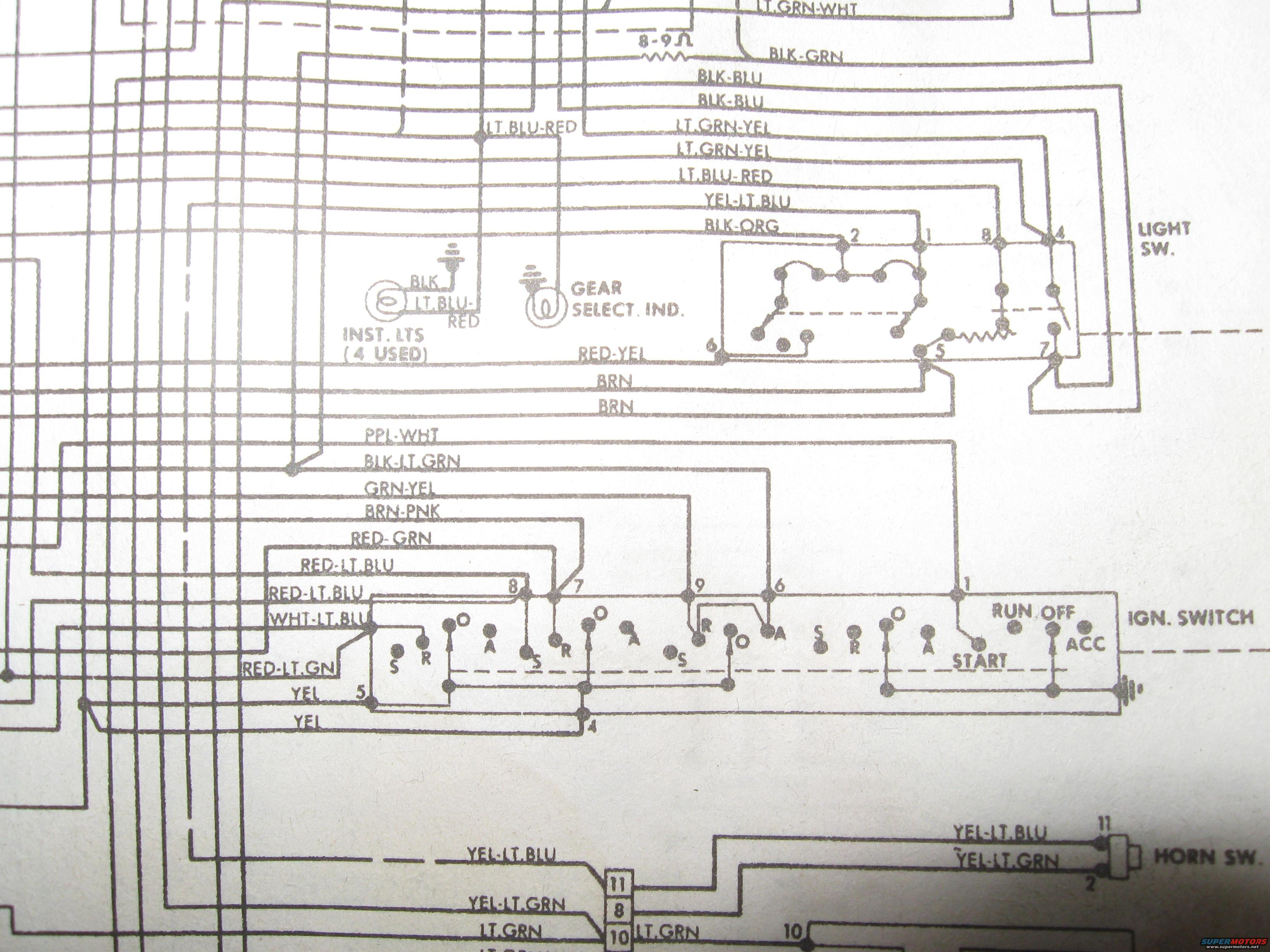
Ford Wiring Diagram - Ignition Switch, Light Switch & Horn Wire Colors
Reference · 1980-1986 BroncoAll 92 wiring diagrams
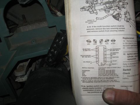

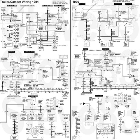
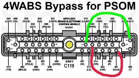
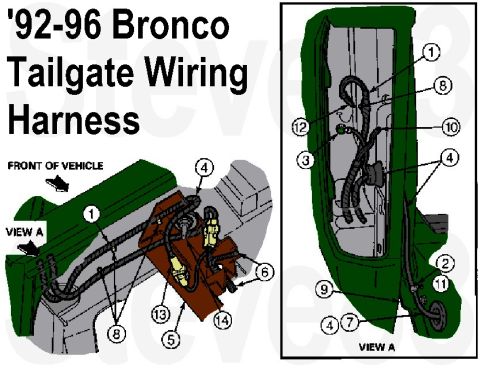



Vehicle wiring diagram showing color-coded leads routed to the ignition switch, light switch, gear-select indicator and horn switch.
Part of 1980-1986 Ford Bronco Wiring Diagrams
This document is a close-up photograph of a section of a Ford factory-style wiring diagram, apparently from a printed shop manual or wiring schematic sheet. The visible portion covers the instrument panel and steering column electrical circuits, including the headlight switch (LIGHT SW.) with numbered terminals 1, 2, 4, 5, 6, 7, 8 and an internal rheostat/resistor, the ignition switch (IGN. SWITCH) with its terminal numbers (1, 4, 5, 6, 7, 8, 9) and key positions (START, RUN, OFF, ACC) with internal contact designations S, R, O, A, the instrument cluster illumination lamps (INST. LTS, 4 USED), the gear selector indicator lamp (GEAR SELECT. IND.), and the horn switch (HORN SW., terminals 11 and 2). Wire color codes are printed along each conductor, including LT.GRN-WHT, BLK-GRN, BLK-BLU, LT.BLU-RED, LT.GRN-YEL, YEL-LT.BLU, BLK-ORG, RED-YEL, BRN, PPL-WHT, BLK-LT.GRN, GRN-YEL, BRN-PNK, RED-GRN, RED-LT.BLU, WHT-LT.BLU, RED-LT.GN, YEL, YEL-LT.GRN, and LT.GRN. An 8-9 ohm resistance wire is noted near the top. A reader can use it to trace wire colors and terminal numbers for the light switch, ignition switch, instrument lamps, and horn circuits.
Is this accurate? Sign in to help verify it.
Frequently asked questions
- What are the key positions shown on the ignition switch in this diagram?
- The ignition switch is shown with START, RUN, OFF, and ACC positions, with internal contacts labeled S, R, O, and A across the switch.
- How many instrument panel lights does this diagram show?
- The diagram notes 'INST. LTS (4 USED)', indicating four instrument lights, wired with BLK and LT.BLU-RED wires.
- What wire colors connect to the horn switch?
- The horn switch is fed by a YEL-LT.BLU wire at terminal 11 and a YEL-LT.GRN wire at terminal 2.
- What resistance value is marked in the circuit near the top of the diagram?
- A resistance of 8-9 ohms (8-9Ω) is marked in the wire between the LT.GRN-WHT and BLK-GRN circuits.
- What terminals are shown on the light switch?
- The light switch (LIGHT SW.) shows terminals numbered 1, 2, 4, 5, 6, 7, and 8, with an internal resistor between terminals 5 and 7 for the instrument light dimmer.






No comments yet.