Home/
Registry/
Ford/
Bronco/
1980-1986/
“Still Pending”/
Photo
supermotors.net/registry/media/825045
Ford 7200 VV Carburetor Air Horn Assembly Exploded View Diagram (Fig. 4.13)
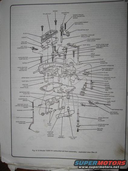
Exploded view of the Motorcraft 7200 VV (variable venturi) carburetor air horn assembly, labeling control vacuum regulator, cold-enrichment rod, metering rods and venturi valves.
This document is a scanned page (page 151) from an automotive repair manual showing Fig. 4.13, an exploded-view diagram of the Model 7200 VV (Variable Venturi) carburetor air horn assembly, referenced to Section 2 of the fuel and exhaust systems chapter. The illustration identifies every component of the air horn in disassembled order, including the upper body, gaskets, dust seals, the control vacuum regulator, cold enrichment rod with its swivel and lever, choke travel stop adjusting screw, choke hinge pin and choke control rod, hot idle compensator, roller bearing, accelerator pump components (swivel, link and swivel assembly, rod, plunger, cup, return spring), venturi valve parts (pivot pin, pivot plug, pivot pin bushing, limiter adjusting screw, overtravel spring), main metering jet assembly, metering rod with pivot pin and spring, float assembly with float hinge pin, fuel inlet valve and seat, inlet fitting, fuel filter, plugs, O-ring, E-clips, screws, nuts, and washers. A reader can use this diagram to identify part names and their relative positions when disassembling, rebuilding, or reassembling a 7200 VV carburetor air horn. The surrounding printed instructional text on the page is largely illegible in this scan.
Is this accurate? Sign in to help verify it.
Frequently asked questions
- What does this diagram show?
- It shows Fig. 4.13, an exploded view of the Model 7200 VV carburetor air horn assembly with all components labeled, referenced to Section 2 of the manual chapter.
- What accelerator pump parts are identified in the 7200 VV air horn?
- The diagram labels the accelerator pump swivel, accelerator pump link and swivel (assembly), accelerator pump rod, accelerator pump plunger, accelerator pump cup, and return spring.
- Which venturi valve components are shown?
- The venturi valve, venturi valve pivot pin, venturi valve pivot plug, venturi valve pivot pin bushing, venturi valve limiter adjusting screw, and an overtravel spring.
- Does the diagram show the fuel inlet and filter parts?
- Yes: it labels the fuel filter, gaskets, inlet fitting, fuel inlet seat, and fuel inlet valve along with the float assembly and float hinge pin.
- What choke-related parts are labeled?
- Choke travel stop adjusting screw, choke hinge pin, choke control rod, cold enrichment rod with its swivel and lever, and the control vacuum regulator.
Comments
More from this build









No comments yet.