Home/
Registry/
Ford/
Bronco/
1980-1986/
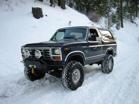
1986 Ford Bronco/
Photo
supermotors.net/registry/media/826862
1986 Ford Bronco Speed Control Amplifier & Wiring Harness Diagram (14401, 9A840)
Reference · 1980-1986 BroncoAll 61 exploded parts diagrams
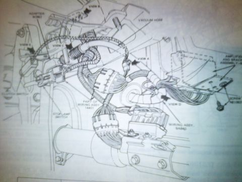
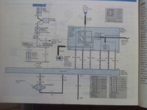
Assembly and routing illustration of a steering-column wiring harness, clutch and stop-lamp switches with views A through D and part callouts.
Part of 1980-1986 Ford Bronco Exploded Parts Diagrams
This is a photographed page from a Ford factory service manual showing an exploded/installation illustration of what appears to be the speed (cruise) control wiring and amplifier installation area near the steering column and brake pedal support. The drawing shows the routing of a wiring harness (identified as part of wiring assembly 14401 and a separate wiring assembly 9A840) with multiple multi-pin connectors, a vacuum hose, an adapter (9C862), the clutch switch, and the stoplamp (brake light) switch. On the right side, an amplifier and bracket assembly is shown in phantom (dashed) lines with a mounting screw (N61062x) indicated. Directional callout arrows labeled VIEW A, VIEW B, VIEW C, VIEW D, and VIEW E point to detail views presumably shown elsewhere in the manual. A reader can learn the general routing of the harness, where the amplifier and bracket mount, the location of the clutch and stoplamp switches relative to the harness, and the Ford base part numbers for the adapter, harness assemblies, and mounting screw. The page itself carries no visible year, model, or engine applicability text.
Is this accurate? Sign in to help verify it.
Frequently asked questions
- What wiring assembly part numbers are shown in this diagram?
- The diagram labels 'PART OF WIRING ASSY. 14401' and 'WIRING ASSY. 9A840'.
- What switches are identified in this illustration?
- The clutch switch and the stoplamp switch are both labeled near the pedal/column area.
- What part number is the adapter shown at the top of the diagram?
- The adapter is labeled 9C862.
- How is the amplifier mounted?
- An amplifier and bracket assembly is shown at the right in dashed outline, secured with a screw (part number beginning N61062, last characters illegible).
- Are there additional detail views referenced?
- Yes, arrows labeled VIEW A, VIEW B, VIEW C, VIEW D, and VIEW E point to detail views presumably shown on other pages.
No comments yet.