SuperMotors SuperMotors SUPERMOTORS Search: try “orange Bronco on 35s”
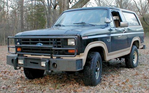
Home/ Registry/ Ford/ Bronco/ 1980-1986/ 1986 Ford Bronco/ Photo supermotors.net/registry/media/826567

Speed control manual page 137 with circuit description and compo…

Speed control manual page 137 with circuit description and component location table
Speed control manual page 137 with circuit description and component location tableOriginal file
Speed control manual page 137 with circuit description and component location table

Reference · 1980-1986 BroncoAll 32 manual pages

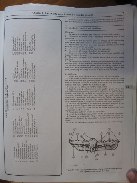
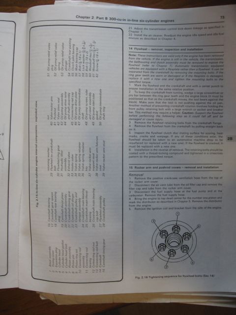
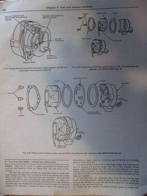
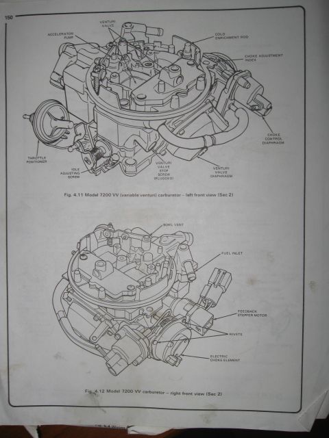
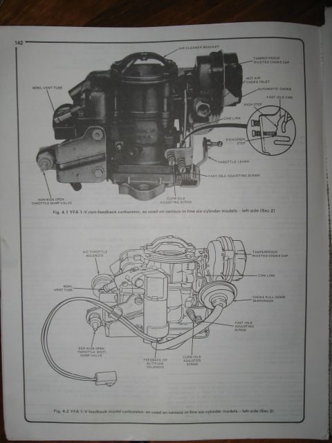
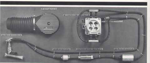
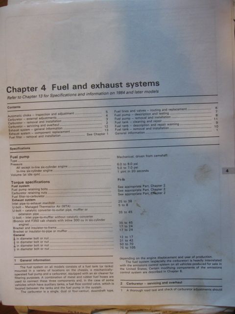
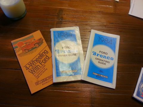
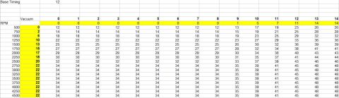
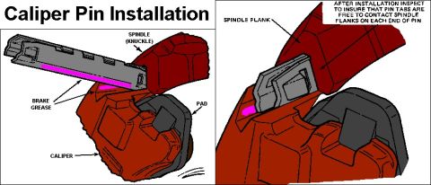
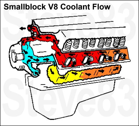
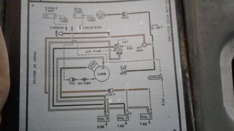
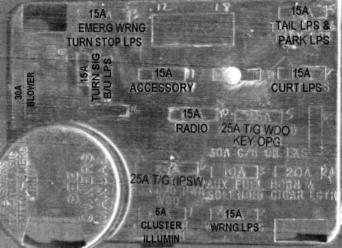
Speed control manual page 137 with circuit description and component location table Ford 6.9L V-8 Diesel Engine Right Side Diagram - VIN & VECI Decal Location Spring rate table in Spanish comparing K constant lb/pulg, wire diameter, coil count and spring diameter Ford 300 Inline Six Manifold Removal/Install & Bolt Torque Sequence - Manual Pg 71 Ford 300 Inline Six Engine Exploded View & Flywheel Removal - Manual Page 73 Ford Bronco Carburetor Choke Cap & Fuel Line Replacement - Manual Page 156 Ford 7200 VV Variable Venturi Carburetor Diagram - Component Callouts (Manual Pg 150) YFA 1-V Carburetor Diagrams - Feedback & Non-Feedback, Inline Six (Ford Bronco) Ford 3G Alternator Output Curves - 95/130 Amp, Leece-Neville 165A, Mitsubishi 215A AirSensors TBI Fuel Flow Path Diagram - EFI Fuel System Component Layout Ford Transmission Pan Identification Chart - C4, C5, C6, AOD, E4OD, 4R70W Ford Bronco/F-Series Fuel & Exhaust Systems - Haynes Ch. 4 Specs & Torque 32manual pages1980-1986 Ford Bronco More reference 1986 Ford Bronco Speed Control (Cruise) Wiring Diagram - Servo & AmplifierWiring diagram 1986 Ford Bronco Speed Control Amplifier & Wiring Harness Diagram (14401, 9A840)Exploded parts 1984 Ford Bronco Owner Guide, Operating Guide & 4-Wheeling With Ford BookletsBrochure Ford Bronco Ignition Timing Curve Table - RPM vs Vacuum Advance (12° Base)Spec plate Ford Bronco Sliding Caliper Pin Installation Diagram - Brake Grease & Pin TabsService procedure Smallblock V8 Coolant Flow Diagram - Ford Engine Cooling Path SchematicSchematic Ford Axle Brake Flange Dimensions Diagram - Small/Big Ford, Bronco, 8.8" TypesBlueprint 1985 Ford Bronco Vacuum Hose Routing Diagram - EGR, TAB/TAD Solenoids, CanisterVacuum routing Ford F-250 Air Cleaner Installation Diagram - Duct, Valve & Torque SpecsTorque spec 1982-83 Ford Bronco Fuse Box Cover Diagram - Fuse Positions & Amp RatingsFuse chart

Page 137, Speed Control: how the circuit works and a component location table listing connectors C125, C305, C714, C753 and splice S406.

Part of 1980-1986 Ford Bronco Manual Pages

AI caption · Photo 216 of 239

,.........;WW __..m.wmzm::; ._M ..... . mm m -..l .m m mum mam1mm mwmv..m......n. mumwumn SPEED CONTROL 137 M cnmnsm locnhm z ,. ..... nu

Is this accurate? Sign in to help verify it.
Comments

No comments yet.

More 1980-1986 Broncos