1996 Ford Probe 2.5L PCM Connector C245 Pinout - Automatic Transaxle Wiring

Reference · 1993-1997 ProbeAll 65 wiring diagrams
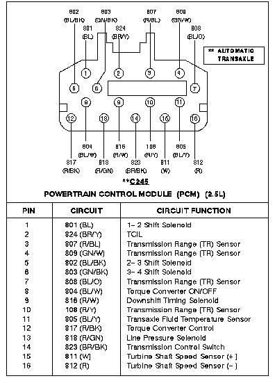









Powertrain control module connector pinout showing color-coded pins and a circuit-function reference table.
Part of 1993-1997 Ford Probe Wiring Diagrams
This document is a connector pinout diagram and table for connector C245 on the Powertrain Control Module (PCM) of a vehicle equipped with the 2.5L engine and automatic transaxle. The diagram shows a 16-pin PCM connector with the physical arrangement of pins 1 through 16 and their associated circuit numbers and wire colors (e.g., 801 BL, 802 BL/BK, 824 BR/Y). The accompanying table lists each pin, its circuit number and wire color, and its circuit function. Circuits covered are all related to automatic transaxle control: 1-2, 2-3, and 3-4 shift solenoids; the TCIL (transmission control indicator lamp); four Transmission Range (TR) sensor circuits; torque converter ON/OFF and torque converter control; downshift timing solenoid; transaxle fluid temperature sensor; line pressure solenoid; transmission control switch; and turbine shaft speed sensor positive and negative leads. A note on the diagram indicates the connector applies to the automatic transaxle. A reader can use this document to identify wire colors and pin locations for diagnosing automatic transmission electrical circuits at the PCM connector C245 on the 2.5L application, which the uploader identifies as belonging to a 1996 Ford Probe.
Is this accurate? Sign in to help verify it.
Frequently asked questions
- What connector does this diagram show?
- Connector C245 at the Powertrain Control Module (PCM) for the 2.5L engine with automatic transaxle.
- Which pin controls the 1-2 shift solenoid?
- Pin 1, circuit 801 with a blue (BL) wire, is the 1-2 Shift Solenoid circuit.
- What wire colors are used for the turbine shaft speed sensor?
- Pin 15, circuit 811 (W, white) is the Turbine Shaft Speed Sensor (+) and pin 16, circuit 812 (R, red) is the Turbine Shaft Speed Sensor (-).
- Which pins connect to the Transmission Range (TR) sensor?
- Pins 3 (807 R/BL), 4 (809 GN/W), 7 (808 BL/O), and 10 (108 R/Y) are Transmission Range (TR) Sensor circuits.
- What circuit is the transaxle fluid temperature sensor on?
- Pin 11, circuit 805 with a blue/yellow (BL/Y) wire.






No comments yet.