Ford Probe PCM Power Relay & FPRC Solenoid Wiring Diagram - ECM Circuit
Reference · 1993-1997 ProbeAll 65 wiring diagrams
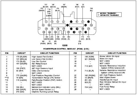
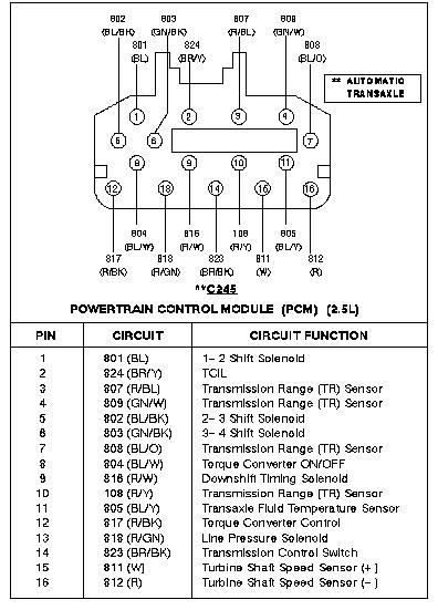
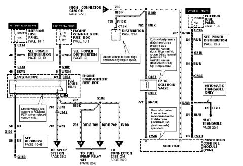
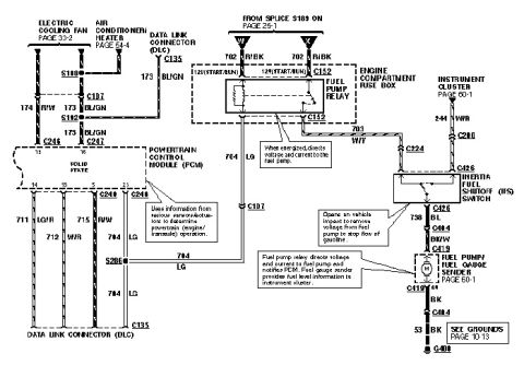
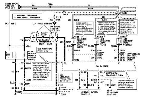
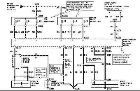
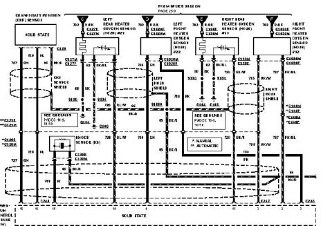









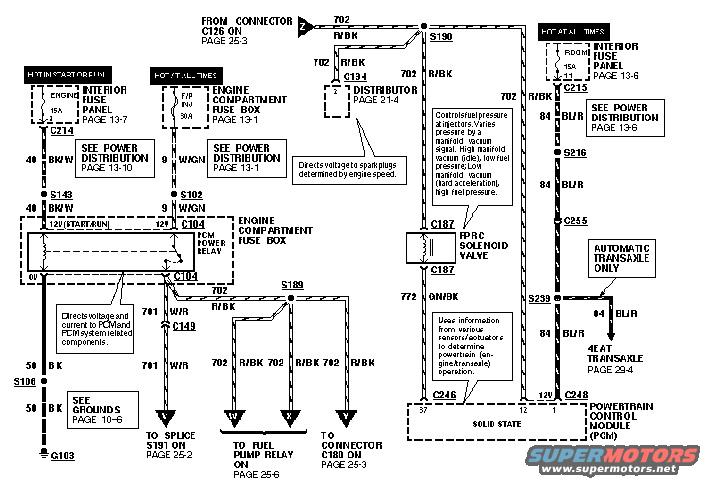
Wiring diagram showing distributor, FPRC solenoid valve, fuse boxes and powertrain control module connections.
Part of 1993-1997 Ford Probe Wiring Diagrams
This document is a scanned page from a Ford wiring diagram (EVTM-style) showing power distribution and control circuits for the Powertrain Control Module (PCM) on a Ford Probe. It depicts the PCM power relay located in the engine compartment fuse box, fed by a 15A ENGINE fuse in the interior fuse panel (hot in start or run, circuit 40 BK/W) and a 30A F/P INJ fuse in the engine compartment fuse box (hot at all times, circuit 9 W/GN). Relay output circuit 702 R/BK feeds the distributor (connector C134), the fuel pump relay (via splice S189), and connector C180; circuit 701 W/R goes to splice S191. A 15A ROOM fuse (hot at all times) supplies circuit 84 BL/R through connectors C215, S216, and C255 to the PCM and, on automatic transaxle vehicles, to the 4EAT transaxle. The FPRC (fuel pressure regulator control) solenoid valve is shown on circuit 772 GN/BK at connector C187, with a note explaining it varies fuel pressure based on manifold vacuum. Grounding is via circuit 50 BK through splice S106 to ground G103. The PCM connects at C246 (pins 37, 12, 1) and C248. Cross-references point to pages 13-1, 13-6, 13-7, 13-10, 10-6, 21-4, 25-2, 25-3, 25-6, and 29-4.
Is this accurate? Sign in to help verify it.
Frequently asked questions
- What fuses power the PCM power relay on the Ford Probe?
- Per the diagram, the PCM power relay in the engine compartment fuse box is fed by a 15A ENGINE fuse in the interior fuse panel (hot in start or run, circuit 40 BK/W) and a 30A F/P INJ fuse in the engine compartment fuse box (hot at all times, circuit 9 W/GN).
- What wire color feeds the fuel pump relay and distributor from the PCM power relay?
- Circuit 702 R/BK (red/black) runs from the PCM power relay through splices S190 and S189 to the distributor (C134), the fuel pump relay (page 25-6), and connector C180 (page 25-3).
- What does the FPRC solenoid valve do according to this diagram?
- It controls fuel pressure at the injectors, varying pressure by a manifold vacuum signal: high manifold vacuum (idle) gives low fuel pressure, low manifold vacuum (hard acceleration) gives high fuel pressure. It connects via C187 on circuit 772 GN/BK.
- Where does the PCM ground on this circuit?
- Ground circuit 50 BK runs through splice S106 to ground point G103 (see Grounds, page 10-6).
- What circuit feeds the 4EAT automatic transaxle in this diagram?
- Circuit 84 BL/R, fed by a 15A ROOM fuse (hot at all times) in the interior fuse panel, splits at splice S239 to feed the 4EAT transaxle (page 29-4) on automatic transaxle models only.






No comments yet.