Ford TFI Ignition Module Comparison: Gray vs Black, Remote & Distributor Pinouts

Reference · 1987-1991 BroncoAll 112 schematics


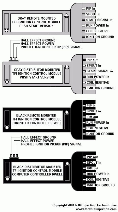










RJM Injection TFI ignition control module connector pinout diagrams for gray and black remote and distributor-mounted versions.
Part of 1987-1991 Ford Bronco Schematics
This schematic compares four variants of the Ford TFI (Thick Film Ignition) ignition control module, showing each module's shape, mounting style, and complete connector pinout. Two gray "Push Start" versions are shown: a remote-mounted module (pins: PIP in, SPOUT in, START SIGNAL in, RUN POWER in, COIL NEGITIVE [sic], IGNITION GROUND) and a distributor-mounted module with the same harness pins except PIP out, plus a three-pin distributor interface (HALL EFFECT GROUND, HALL EFFECT POWER, PROFILE IGNITION PICKUP (PIP) SIGNAL). Two black "Computer Controlled Dwell" versions are also shown: a remote-mounted module (PIP in, SPOUT in, IDM out, RUN POWER in, COIL NEGITIVE, IGNITION GROUND) and a distributor-mounted module (PIP out, SPOUT in, IDM out, RUN POWER in, COIL NEGITIVE, IGNITION GROUND) that also carries the three-pin Hall effect distributor connections. The key functional differences visible are that gray Push Start modules use a START SIGNAL input where black CCD modules provide an IDM output, and that distributor-mounted units output PIP while remote-mounted units receive PIP as an input. The diagram is credited Copyright 2004 RJM Injection Technologies, www.fordfuelinjection.com. It serves as a quick identification and pinout reference for distinguishing gray vs. black and remote vs. distributor-mounted TFI modules.
Is this accurate? Sign in to help verify it.
Frequently asked questions
- What is the difference between the gray and black TFI ignition control modules?
- Per the diagram, gray modules are the Push Start version and have a START SIGNAL in pin, while black modules are the Computer Controlled Dwell version and have an IDM out pin instead. Both types share PIP, SPOUT in, RUN POWER in, COIL NEGITIVE, and IGNITION GROUND pins.
- What is the pin difference between remote-mounted and distributor-mounted TFI modules?
- Remote-mounted modules show 'PIP in' on the connector, while distributor-mounted modules show 'PIP out' and additionally have a three-pin distributor interface: HALL EFFECT GROUND, HALL EFFECT POWER, and PROFILE IGNITION PICKUP (PIP) SIGNAL.
- What are the six connector pins on the black remote-mounted TFI module?
- PIP in, SPOUT in, IDM out, RUN POWER in, COIL NEGITIVE, and IGNITION GROUND.
- What does PIP stand for in this diagram?
- Profile Ignition Pickup, as labeled on the distributor-mounted modules' 'PROFILE IGNITION PICKUP (PIP) SIGNAL' pin.
- Who produced this TFI module comparison diagram?
- It is marked Copyright 2004 RJM Injection Technologies, www.fordfuelinjection.com.






No comments yet.