SuperMotors SuperMotors SUPERMOTORS Search: try “orange Bronco on 35s”
Home/ Registry/ Ford/ Bronco/ 1987-1991/ “Eddie Bauer”/ Photo supermotors.net/registry/media/841896

Ford 5.0L HO / 5.8L V8 Firing Order Diagram 1-3-7-2-6-5-4-8 & Plug Wire Routing

5.0L/5.8L HO firing order and spark plug wire routing diagram
5.0L/5.8L HO firing order and spark plug wire routing diagramOriginal file
5.0L/5.8L HO firing order and spark plug wire routing diagram

Reference · 1987-1991 BroncoAll 112 schematics
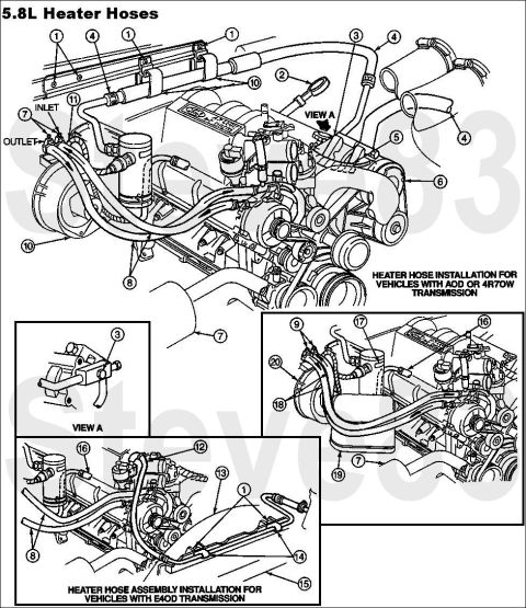
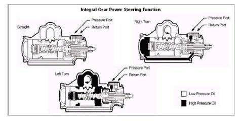
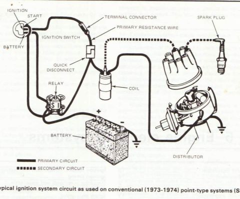
Ford 5.8L Heater Hose Routing Diagram - AOD, 4R70W & E4OD (Bronco/F-Series) Ford 300ci 4.9L I6 Firing Order & Spark Plug Wire Routing Diagram Ford V8 & 6-Cylinder Firing Order Diagrams - 351/400 V8, Other V8, Inline Six Ford 5.0L HO / 5.8L V8 Firing Order Diagram 1-3-7-2-6-5-4-8 & Plug Wire Routing Ford TFI Ignition Module Comparison: Gray vs Black, Remote & Distributor Pinouts ABS Electric High Power Master Cylinder w/ Inline Accumulator Diagram #10-56-9 Ford V8 & Inline 6 Firing Order Diagrams - 351/400, Other V8s, 6 Cylinder Ford 5.8L Secondary Air (Thermactor) System Diagram - Component Locations Ford 5.0 Fox Mustang Short Belt Routing Diagram - 84.5" & 70.5" vs Stock Integral Gear Power Steering Fluid Flow Diagram - Ford Bronco Gear Box Schematic 112schematics1987-1991 Ford Bronco More reference 1973-1974 Ford Point-Type Ignition System Circuit Diagram - Coil & DistributorWiring diagram Ford Canister Purge Regulator Valve (CANP 9C915) Test Procedure - Figure 11Service procedure Ford 5.8L important engine information decal with 10° BTDC timing check and ASF-32C plugSpec plate Ford 5.0L V8 PCV Valve & Hose Routing Diagram - 9A474, 6B890, 6A664Exploded parts Ford 5.0L/5.8L Air Throttle Body Assembly Diagram - Canister Purge Ports & TPSManual page 1990 Bronco Major Standard Equipment sheet with interior features and functional specs by trimBrochure Borgeson Steering Intermediate Shaft Measurement Diagram - U-Joint Length B & CBlueprint Ford Thermactor Combination Valve Diagram - Air Bypass/Control Ports LabeledVacuum routing 1990 Ford Bronco Fuse Panel Diagram: Fuse Positions, Amps & Circuits (11-2)Fuse chart Ford V8 Intake Manifold Bolt Tightening Sequence Diagram - Stud LocationsTorque spec

Ford 5.0L/5.8L HO firing-order diagram showing spark plug wire routing and cylinder numbering to prevent crossfire.

Part of 1987-1991 Ford Bronco Schematics

AI caption · Photo 304 of 1787

This schematic shows the firing order and spark plug wire routing for Ford 5.0L HO and 5.8L V8 engines. The diagram depicts the engine from above with the distributor at the front, showing both cylinder banks: cylinders 1 through 4 on one bank and 5 through 8 on the other. Callout circles identify each cylinder position, and the drawing illustrates how the spark plug wires should be routed from the distributor cap to each cylinder. A prominent attention note warns that to prevent crossfire (induced misfiring between adjacent wires), the spark plug wires for cylinders 1, 3, 5 and 6 must be routed exactly as shown in the illustration. The document also includes a timing scale illustration marked TC, 10, 20, and 30 with an arrow indicating the 10-degree mark, and states that base ignition timing is 10 degrees. The firing order is given clearly at the bottom: 1-3-7-2-6-5-4-8, which is the HO firing order distinct from the standard 5.0L order. This reference is useful when replacing spark plug wires, installing a distributor, or diagnosing misfires on these engines.

Is this accurate? Sign in to help verify it.

Frequently asked questions

What is the firing order for the Ford 5.0L HO and 5.8L engines?
The firing order is 1-3-7-2-6-5-4-8, as stated at the bottom of the diagram.
What is the base ignition timing for these engines?
The document states base timing is 10°, shown by an arrow at the 10 mark on the timing scale (TC 10 20 30).
Why do spark plug wires 1, 3, 5 and 6 need special routing?
The attention note says to prevent crossfire, the spark plug wires for cylinders 1, 3, 5 and 6 must be routed as shown in the diagram.
Which engines does this firing order diagram apply to?
It applies to the 5.0L HO and 5.8L engines, per the diagram's title.

Comments

No comments yet.

More 1987-1991 Broncos