Ford V8 & Inline 6 Firing Order Diagrams - 351/400, Other V8s, 6 Cylinder

Reference · 1987-1991 BroncoAll 112 schematics
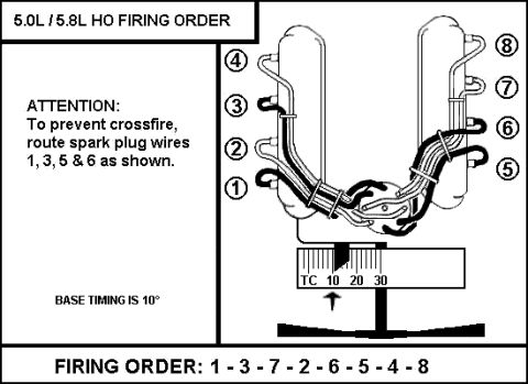
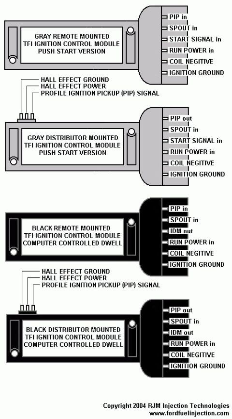
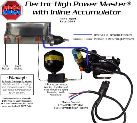
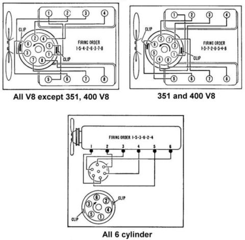









Ford firing-order and distributor cap wiring diagrams for V8 (351/400 and others) and 6-cylinder engines.
Part of 1987-1991 Ford Bronco Schematics
This schematic shows spark plug wire routing and firing order diagrams for three Ford engine families, each drawn as a top view of the engine with fan, distributor cap, and spark plug wire paths. The first diagram, labeled 'All V8 except 351, 400 V8', shows firing order 1-5-4-2-6-3-7-8 with the distributor cap terminal layout and the routing of each plug wire from cap tower to cylinder. The second diagram, labeled '351 and 400 V8', shows firing order 1-3-7-2-6-5-4-8 with its corresponding cap layout and wire routing. The third diagram, labeled 'All 6 cylinder', shows firing order 1-5-3-6-2-4 for the inline six, with plug wires running from the distributor to cylinders 1 through 6 along the head, plus an enlarged distributor cap detail showing tower positions. Each cap drawing marks the locations of the two retaining CLIPs, which help orient the cap correctly. A reader can use this document to identify the correct firing order for their engine, determine which distributor cap tower connects to which cylinder, and route or re-route spark plug wires correctly after cap or wire replacement. The document itself gives no year, make, or part numbers, though it was filed with a 1990 Ford Bronco.
Is this accurate? Sign in to help verify it.
Frequently asked questions
- What is the firing order for Ford V8 engines except the 351 and 400?
- The diagram labeled 'All V8 except 351, 400 V8' shows a firing order of 1-5-4-2-6-3-7-8.
- What is the firing order for the Ford 351 and 400 V8?
- The diagram labeled '351 and 400 V8' shows a firing order of 1-3-7-2-6-5-4-8.
- What is the firing order for the Ford 6-cylinder engine?
- The 'All 6 cylinder' diagram shows a firing order of 1-5-3-6-2-4.
- How do I know which distributor cap tower goes to which cylinder?
- Each diagram shows the numbered towers on the distributor cap and traces each spark plug wire to its numbered cylinder; the cap's two CLIP locations are marked to help orient the cap.






No comments yet.