1989 Ford Bronco E4OD Transmission Wiring Diagram - EEC Module Pins (Pg 44)
Reference · 1987-1991 BroncoAll 175 wiring diagrams
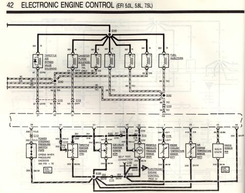
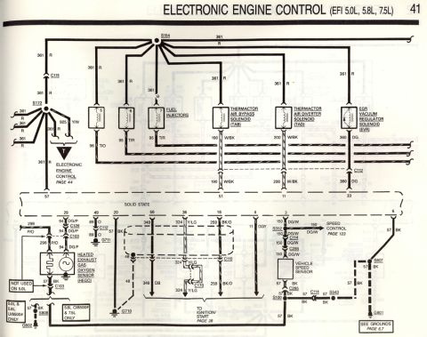
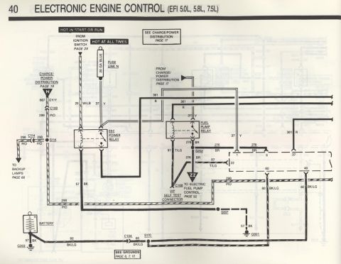
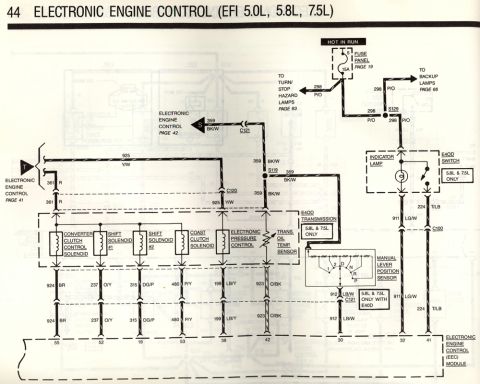
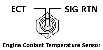
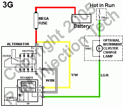
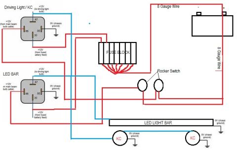
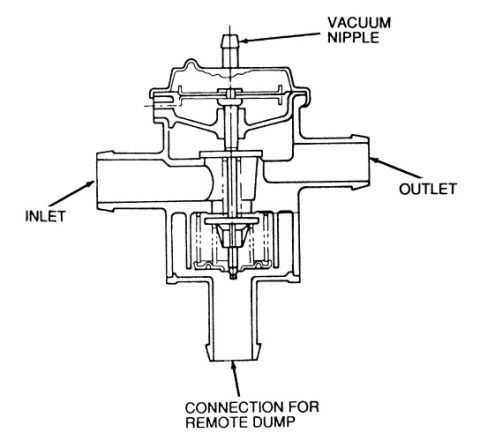









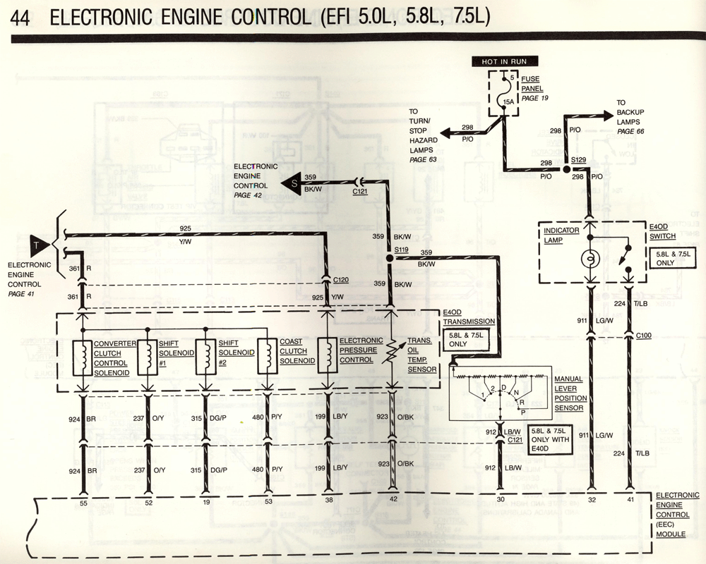
Wiring diagram showing EEC electronic engine control circuits, transmission solenoids, and E4OD components with color-coded wires.
Part of 1987-1991 Ford Bronco Wiring Diagrams
This is page 44 of a Ford factory-style wiring diagram set, titled "Electronic Engine Control (EFI 5.0L, 5.8L, 7.5L)," covering the E4OD automatic transmission electrical circuits as they connect to the Electronic Engine Control (EEC) module. Power comes from Fuse 5 (15A) in the fuse panel (page 19) on a Hot-In-Run circuit 298 P/O, which also feeds the turn/stop hazard lamps (page 63) and backup lamps (page 66) via splice S129. The diagram shows the E4OD transmission internal components, converter clutch control solenoid, shift solenoids #1 and #2, coast clutch solenoid, electronic pressure control, and transmission oil temperature sensor, all noted as 5.8L & 7.5L only. It maps each circuit to the EEC module pins: 924 BR (pin 55), 237 O/Y (pin 52), 315 DG/P (pin 19), 480 P/Y (pin 53), 199 LB/Y (pin 38), 923 O/BK (pin 42), 912 LB/W (pin 30), 911 LG/W (pin 32), and 224 T/LB (pin 41). Also shown are the manual lever position sensor (1, 2, D, N, R, P), an E4OD overdrive-cancel switch with indicator lamp, connectors C100, C120, C121, and splices S119/S129, with cross-references to EEC diagram pages 41 and 42.
Is this accurate? Sign in to help verify it.
Frequently asked questions
- Which fuse powers the E4OD transmission circuit on this diagram?
- Fuse 5, a 15A fuse in the fuse panel (referenced to page 19), on a Hot In Run circuit feeding wire 298 P/O.
- What EEC module pins connect to the E4OD transmission solenoids?
- Pin 55 (wire 924 BR), pin 52 (237 O/Y), pin 19 (315 DG/P), pin 53 (480 P/Y), pin 38 (199 LB/Y), pin 42 (923 O/BK), pin 30 (912 LB/W), pin 32 (911 LG/W), and pin 41 (224 T/LB).
- Which engines does the E4OD transmission apply to in this diagram?
- The E4OD transmission, E4OD switch, and manual lever position sensor circuits are marked '5.8L & 7.5L ONLY' (with E4OD).
- What components are inside the E4OD transmission on this diagram?
- Converter clutch control solenoid, shift solenoid #1, shift solenoid #2, coast clutch solenoid, electronic pressure control, and transmission oil temperature sensor.
- What wire feeds the backup lamps from this circuit?
- Wire 298 P/O branches at splice S129 to the backup lamps (see page 66) and also to the turn/stop hazard lamps (page 63).






No comments yet.