1989 Ford Bronco EEC Wiring Diagram Pg 40 - EEC & Fuel Pump Relay Power (EFI)
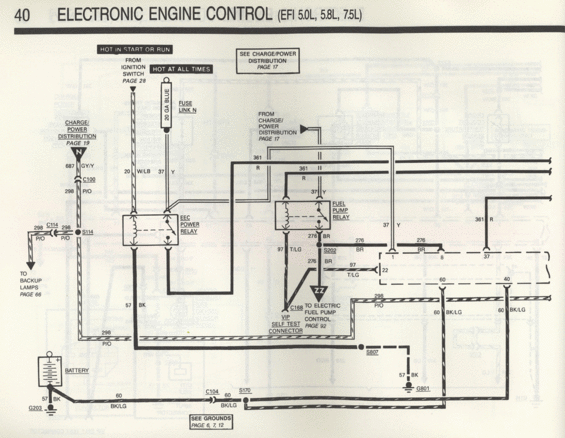
Wiring diagram of EEC power relay, fuel pump relay, and battery feed circuits for EFI 5.0L/5.8L/7.5L engines.
Part of 1987-1991 Ford Bronco Wiring Diagrams
This is page 40 of a Ford factory-style wiring diagram set, covering the Electronic Engine Control (EEC) power distribution for EFI 5.0L, 5.8L, and 7.5L engines. The diagram shows how the EEC Power Relay and Fuel Pump Relay receive power: a 'Hot in Start or Run' feed comes from the ignition switch (page 28) on circuit 20 W/LB, and a 'Hot at All Times' feed passes through Fuse Link N (20 GA Blue) on circuit 37 Y. Circuit 361 R comes from charge/power distribution (page 17), and circuit 687 GY/Y and 298 P/O route through connector C100 from charge/power distribution (page 19). The EEC power relay output feeds circuit 361 R and 37 Y to the processor connector (pins 1, 8, 22, 37, 40, 60 shown). The fuel pump relay output on circuit 97 T/LG feeds the electric fuel pump control (page 92) via connector C168 and the VIP self-test connector, with circuit 276 BR at splice S202. Grounds are shown through circuits 57 BK and 60 BK/LG via splices S807, S170, connector C104, and grounds G801 and G203, with a battery symbol and reference to grounds pages 6, 7, and 12. Wire circuit numbers, colors, connector, splice, and ground identifiers are labeled throughout.
Is this accurate? Sign in to help verify it.
Frequently asked questions
- What engines does this EEC wiring diagram page cover?
- The page is titled 'Electronic Engine Control (EFI 5.0L, 5.8L, 7.5L)', so it covers the EFI 5.0L, 5.8L, and 7.5L engines.
- What powers the EEC power relay?
- It receives a 'Hot in Start or Run' feed from the ignition switch (see page 28) on circuit 20 W/LB, and a 'Hot at All Times' feed through Fuse Link N (20 GA Blue) on circuit 37 Y. Circuit 361 R comes from charge/power distribution (page 17).
- What fuse link protects the always-hot feed to the relays?
- Fuse Link N, shown as 20 GA Blue, protects the 'Hot at All Times' circuit 37 Y.
- What wire circuit feeds the electric fuel pump from the fuel pump relay?
- Circuit 97 T/LG (tan/light green) from the fuel pump relay goes to the electric fuel pump control (page 92), passing through connector C168 and the VIP self-test connector, with circuit 276 BR at splice S202.
- Where are the grounds for this circuit shown?
- Grounds G801 (via circuit 57 BK through splice S807) and G203 (via 57 BK at the battery) are shown, with 60 BK/LG routing through connector C104 and splice S170. The diagram says 'See Grounds Page 6, 7, 12'.
Comments
More from this build














No comments yet.