1995 Ford Bronco 5.8L Fuel Pump Wiring Diagram - Engine Controls Page 25-6

Reference · 1987-1991 BroncoAll 175 wiring diagrams
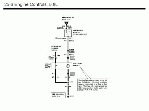
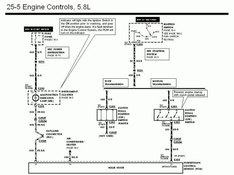
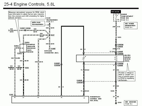
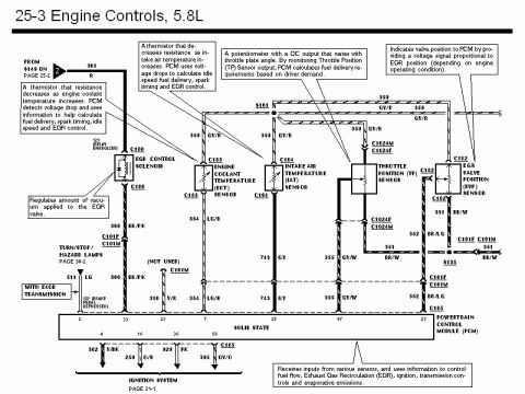
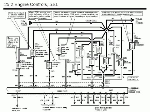











Wiring diagram of 5.8L engine controls showing inertia fuel shutoff switch and fuel pump module sender circuits.
Part of 1987-1991 Ford Bronco Wiring Diagrams
This document is page 25-6 of a Ford wiring diagram set, covering the Engine Controls for the 5.8L engine, specifically the fuel pump circuit. Power arrives on circuit 238 (DG/Y wire) from connector C202 (referenced to page 25-1), showing 12V when the fuel pump relay is energized. It passes through connector C271 to the Inertia Fuel Shutoff switch, which opens on impact, then continues on circuit 787 (PK/BK wire) through connectors C205F/C205M and C441F/C441M to the Fuel Pump Module. The fuel gauge sender portion connects to the Instrument Cluster (page 60-1) via circuit 29 (Y/W wire); the sender is a variable resistor reading 22.5 ohms when the tank is empty and 145 ohms when full. Grounding is via circuit 57 (BK wire) and circuit 80 (O wire) through splice S400 to ground G100 (see Grounds, page 10-3). A callout explains the module supplies fuel under pressure to the fuel rail and injectors, and describes the float-based variable-resistor sender operation. Diagnostic voltage references (12V switch closed, 0V) are marked at test points along the circuit.
Is this accurate? Sign in to help verify it.
Frequently asked questions
- What wire color feeds the inertia fuel shutoff switch on the 5.8L Bronco?
- Circuit 238, a DG/Y (dark green/yellow) wire, feeds the inertia fuel shutoff via connector C271, showing 12V when the relay is energized.
- What circuit runs from the inertia switch to the fuel pump module?
- Circuit 787, a PK/BK (pink/black) wire, runs from the inertia fuel shutoff through connectors C205F/C205M and C441F/C441M to the fuel pump module.
- What resistance should the fuel gauge sender read?
- The sender is a variable resistor: about 22.5 ohms when the tank is empty and 145 ohms when full.
- Where does the fuel pump module ground?
- Through circuit 57 (BK wire) and circuit 80 (O wire) via splice S400 to ground G100; see Grounds on page 10-3.
- What does the inertia fuel shutoff switch do?
- It opens on impact, cutting power (circuit 787) to the fuel pump module.






No comments yet.