1995 Ford Bronco 5.8L Engine Controls Wiring Diagram - MAP & O2 Sensor (25-4)
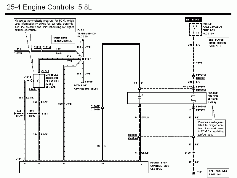
Wiring diagram of 5.8L engine controls showing manifold absolute pressure sensor and heated oxygen sensor circuits to the PCM.
Part of 1987-1991 Ford Bronco Wiring Diagrams
This is page 25-4 of the Engine Controls wiring diagram section for a Ford Bronco with the 5.8L engine (part of a 1995 Bronco wiring diagram set). The schematic covers two engine-control sensors: the Manifold Absolute Pressure (MAP) sensor and the Heated Oxygen Sensor (HO2S), and their connections to the Powertrain Control Module (PCM). The MAP sensor, which the diagram notes measures atmospheric pressure so the PCM can adjust fuel-air ratio, transmission line pressure, and shift scheduling at altitude, connects via circuits 359 GY/R, 358 LG/BK, and 351 BR/W (through splice S163) to PCM pins 46 and 26. Circuit 359 GY/R also runs through splice S137 to the Data Link Connector (DLC, C198F) and, on E4OD-equipped trucks, to the E4OD transmission diagram on page 30-1. The HO2S receives 12V in RUN via circuit 298 P/O from fuse E (15A, hot in run) in the engine compartment fuse box (page 13-4), sends its signal on circuit 89 O to PCM pin 43, uses 74 GY/LB (PCM pin 29), and grounds through circuit 57 BK via splice S100 to ground G101. Cross-references point to Power Distribution (page 13-4) and Grounds (page 10-2).
Is this accurate? Sign in to help verify it.
Frequently asked questions
- What does the MAP sensor do according to this diagram?
- It measures atmospheric pressure for the PCM, which uses the information to adjust fuel-air ratio, transmission line pressure, and shift scheduling for higher altitude operation.
- What fuse powers the heated oxygen sensor on the 5.8L Bronco?
- Fuse E, a 15A fuse in the engine compartment fuse box (page 13-4), which is hot in RUN, feeds the HO2S 12V through circuit 298 P/O.
- What wire colors connect the MAP sensor to the PCM?
- Circuit 359 GY/R (gray/red) goes to PCM pin 46, circuit 358 LG/BK (light green/black) comes off the sensor, and circuit 351 BR/W (brown/white) runs through splice S163 to PCM pin 26.
- How is the heated oxygen sensor grounded?
- Through circuit 57 BK (black), which passes through splice S100 to ground G101 (see Grounds page 10-2).
- Which PCM pins are shown on this page?
- PCM pins 45, 26, 46, 43, and 29 are shown, with pin 43 receiving the O2 sensor signal on circuit 89 O and pin 29 connected via 74 GY/LB.
Comments
More from this build














No comments yet.