Ford PMGR Starter Wiring Diagram - Relay, Solenoid & Cable Gauge Instructions

Reference · 1987-1991 BroncoAll 175 wiring diagrams
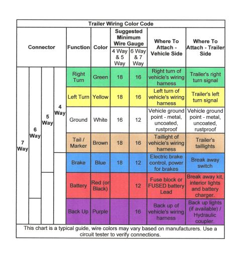
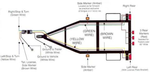


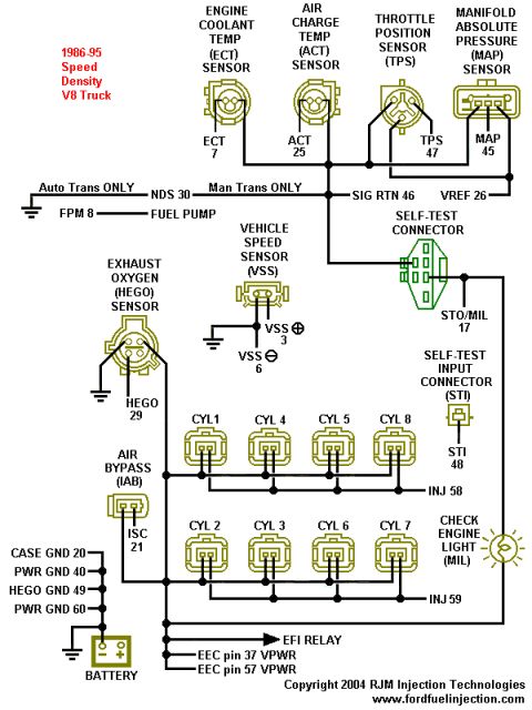
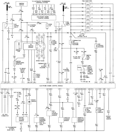











Ford PMGR starter wiring diagram showing battery cable, starter cable, solenoid studs and relay terminal connections.
Part of 1987-1991 Ford Bronco Wiring Diagrams
This document is a labeled wiring illustration titled 'Ford (PMGR) Starter Wiring Instructions,' showing how to wire a Ford PMGR (Permanent Magnet Gear Reduction) starter motor. The diagram depicts a fender-mounted starter relay at the top and the PMGR starter motor with its integral solenoid at the bottom. Callouts indicate that the battery positive cable connects to one large stud of the relay, while the main starter cable, specified as #4 to 2 gauge, runs from the relay's other large post down to the starter solenoid's main terminal, secured with an 8MM nut. A separate #12 gauge wire runs from the relay to the starter solenoid's 4MM stud, which triggers the solenoid. The relay's small terminal is labeled for connection to the key switch or a push button. A reader can learn the correct cable gauges (#4-2 gauge main cable, #12 gauge trigger wire), fastener sizes (4mm stud, 8mm nut), and overall wiring layout needed to install or retrofit a PMGR starter using the existing fender-mounted relay. No year, model, part numbers, or torque specifications are stated on the document itself.
Is this accurate? Sign in to help verify it.
Frequently asked questions
- What gauge wire connects the relay to the PMGR starter solenoid stud?
- A #12 gauge wire runs from the relay to the 4MM solenoid stud on the starter.
- What size should the main starter cable be?
- The diagram specifies a starter cable of #4 to 2 gauge.
- What size nut secures the main starter cable at the solenoid?
- An 8MM nut secures the cable at the starter motor solenoid.
- Where does the key switch wire connect on a PMGR starter setup?
- The key switch or push button wire connects to the small relay terminal on the fender-mounted starter relay.
- Where does the battery positive cable attach?
- The battery positive cable attaches to one of the large studs on the starter relay.






No comments yet.