Ford EFI Wiring Diagram - EEC-IV Engine Control Module Pinout & Sensors
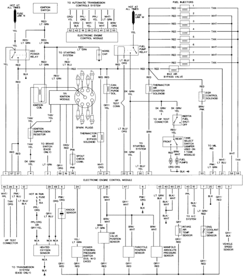
Wiring diagram of the electronic engine control module showing sensor, injector and ignition connections with color-coded wires.
This document is a full-page EFI (electronic fuel injection) wiring schematic centered on the Ford EEC electronic engine control module. It shows the module's numbered connector pins (top row pins such as 1, 57, 37, 4, 2, 56, 16, 36, 51, 31, 22, 8, 30, 11, 33, 17, 21, 59, 58 and bottom row pins 48, 28, 9, 12, 29, 49, 6, 24, 27, 26, 47, 6, 45, 40, 60, 25, 43, 10, 7, 20, 46, 3) with wire color codes for each circuit. Components wired to the module include eight fuel injectors, the idle air bypass valve, fuel pump relay, EEC power relay, TFI ignition module, ignition coil, spark plugs, ignition suppression resistor, canister purge solenoid, thermactor air diverter and bypass solenoids, EGR control solenoid, inertia fuel shut-off, tank select switch and dual fuel pumps, heated oxygen sensor, knock sensor, power steering pressure switch (5.0L w/o E4OD), EGR valve position sensor, throttle position sensor, MAP sensor, intake air temp sensor, engine coolant temp sensor, and vehicle speed sensor. Power sources include fuse links N and W (hot at all times) and fuse 5 (15A, hot in run). E4OD-specific circuits and the VIP test connector are also shown.
Is this accurate? Sign in to help verify it.
Frequently asked questions
- What amperage is the fuse feeding the heated oxygen sensor circuit?
- Fuse 5, a 15A fuse that is hot in run, feeds the circuit shown near the heated oxygen sensor (PPL/ORG wire).
- What wire colors go to the fuel injectors?
- All eight injectors have a RED feed wire; the return wires alternate between TAN (injectors 1, 4, 5, 8) and WHT (injectors 2, 3, 6, 7).
- Which EEC pins connect to the automatic transmission controls system?
- Pins 52, 42, 19, 38, 53, 41, 32, and 55, using wires ORG/YEL, ORG/BLK, PPL/ORG, WHT/YEL, PPL/YEL, TAN/WHT, WHT/LT GRN, and BRN/ORG.
- What wire colors are used for the throttle position sensor?
- The throttle position sensor is shown with GRY/WHT, BRN/WHT, and GRY/RED wires.
- Is there a note about single fuel tank models?
- Yes: the tank select switch is labeled with a note that a jumper is used on 1-tank models.
Comments
More from this build













No comments yet.