1986-95 Ford V8 Truck Speed Density EFI Wiring Schematic - EEC-IV Pinout
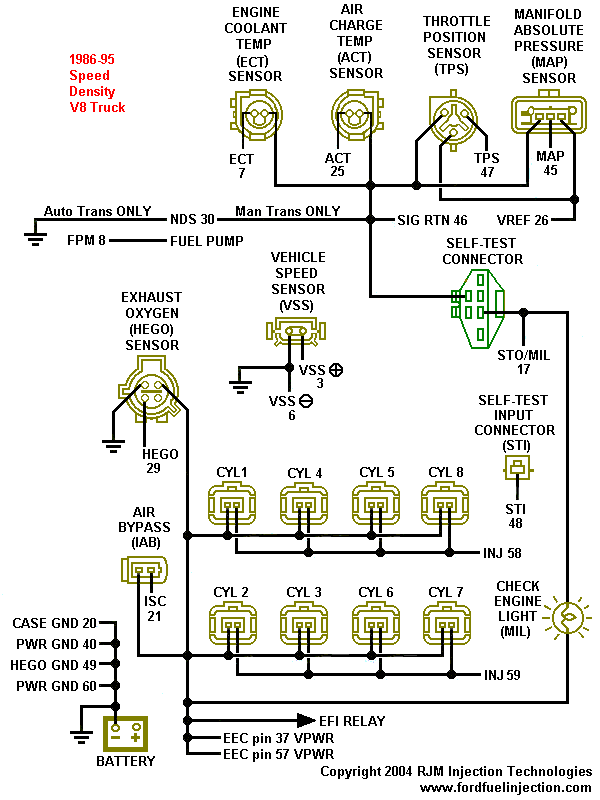
Speed-density V8 truck EFI wiring diagram showing sensors, cylinder injectors, self-test connector and ground circuits.
This document is a color-coded EFI wiring schematic for 1986-95 Ford speed-density V8 trucks, produced by RJM Injection Technologies (fordfuelinjection.com, copyright 2004). It shows the EEC-IV engine control system's sensor and actuator connectors along with their corresponding EEC processor pin numbers. Sensors depicted include the Engine Coolant Temp (ECT, pin 7), Air Charge Temp (ACT, pin 25), Throttle Position Sensor (TPS, pin 47), Manifold Absolute Pressure (MAP, pin 45), Vehicle Speed Sensor (VSS, pins 3 and 6), and Exhaust Oxygen (HEGO, pin 29). Shared signal wiring is shown: SIG RTN (pin 46), VREF (pin 26), and NDS (pin 30, noted as auto trans only, with a ground path for manual trans). Fuel pump monitor (FPM, pin 8), Air Bypass valve (ISC, pin 21), self-test connectors (STO/MIL pin 17, STI pin 48), and the Check Engine Light (MIL) are also included. Injector banks are grouped: cylinders 1, 4, 5, 8 on INJ 58 and cylinders 2, 3, 6, 7 on INJ 59. Grounds are listed as CASE GND 20, PWR GND 40, HEGO GND 49, and PWR GND 60, with battery power routed through the EFI relay to EEC VPWR pins 37 and 57. Connector shapes/pin layouts are illustrated for each component.
Is this accurate? Sign in to help verify it.
Frequently asked questions
- What EEC pin does the MAP sensor connect to on 1986-95 speed density Ford V8 trucks?
- The Manifold Absolute Pressure (MAP) sensor connects to EEC pin 45, with VREF on pin 26 and SIG RTN on pin 46.
- Which injectors are grouped together on the speed density EFI system?
- Cylinders 1, 4, 5, and 8 are driven by INJ pin 58, while cylinders 2, 3, 6, and 7 are driven by INJ pin 59.
- What are the ground pins on the EEC-IV processor in this schematic?
- CASE GND is pin 20, PWR GND is pins 40 and 60, and HEGO GND is pin 49.
- How does the EEC computer receive power in this schematic?
- Battery power flows through the EFI relay to EEC pins 37 and 57 (VPWR).
- What is the NDS pin and does it differ by transmission?
- NDS is pin 30. The diagram notes it applies to auto trans only, while manual trans vehicles have the circuit grounded instead.
Comments
More from this build













No comments yet.