1995 Ford Bronco Engine Compartment Component Location Diagram (FCS-12129-95)

Reference · 1987-1991 BroncoAll 175 wiring diagrams

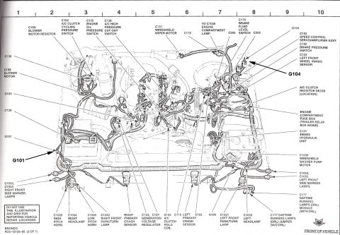
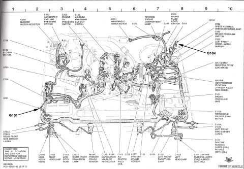











Engine-compartment component-location diagram mapping connectors (C-numbers) and grounds (G100/G101/G104) to physical positions: blower resistor, headlamps, horns, ABS sensors, generator and wiper motor.
Part of 1987-1991 Ford Bronco Wiring Diagrams
This document is a component location view (page 2 of 7) from the Ford factory electrical/vacuum troubleshooting manual FCS-12129-95 for the Bronco. It presents an overhead line drawing of the engine compartment with a numbered grid (columns 1-10) across the top and labeled arrows pointing to electrical connectors, ground points, and components. Identified items include the blower motor and resistor (C168, C169), A/C clutch cycling pressure switch (C162), engine oil pressure switch (C135), A/C high pressure cut out switch (C126), windshield wiper motor (C151), engine compartment lamp (to C1035), brake fluid level switch (C170), speed control servo/amplifier (C152), brake pressure switch (C102), left front wheel 4WABS sensor (C123), 4WABS hydraulic unit (C121), windshield washer pump motor (C1030), engine compartment fuse box (with trailer relay box inside), generator/voltage regulator (C153, C154), A/C clutch field coil (C163), horns (C1005, C1006), headlamps (C1033, C1034), park/turn lamps (C1031, C1032), side marker lamps (C1052-C1055), crash sensors, DRL module and jumper (C177), and ground points G100, G101, G103, and G104. A note states the illustration and grid should not be used for reporting vehicle repair locations.
Is this accurate? Sign in to help verify it.
Frequently asked questions
- Where is the DRL (Daytime Running Lamps) module on a 1995 Bronco?
- The diagram shows the C177 DRL module (with DRL) located on the left front of the engine compartment near the left headlamp area; on trucks without DRL, a C177 DRL jumper is used instead.
- What connector numbers are used for the headlamps and park/turn lamps?
- C1034 right headlamp, C1033 left headlamp, C1032 right front park/turn lamp, and C1031 left front park/turn lamp.
- Where is the engine compartment fuse box and what is inside it?
- It is labeled on the right (driver) side of the engine compartment, and the diagram notes the trailer relay box is inside it.
- Which ground points are shown in the engine compartment?
- Grounds G100, G101, G103, and G104 are identified, with bold arrows highlighting G101 (near the battery area) and G104 (near the left front fender area).
- What connector is the 4WABS hydraulic unit and left front wheel sensor?
- The 4WABS hydraulic unit is connector C121 and the left front wheel 4WABS sensor is connector C123.






No comments yet.