Ford Mini Starter (PMGR) Relay Wiring Diagram - 5-Pin Relay, 20A Fuse, Wire Gauges

Reference · 1987-1991 BroncoAll 175 wiring diagrams



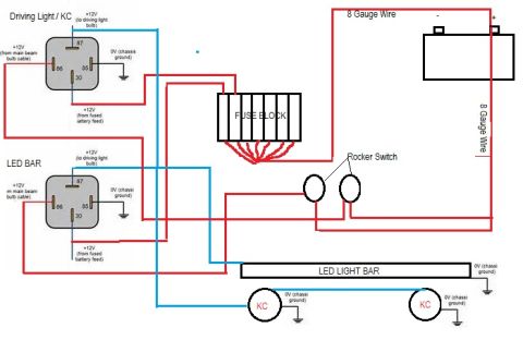










Wiring diagram showing a starter relay with battery, starter solenoid and color-coded 12ga and 18ga circuits.
Part of 1987-1991 Ford Bronco Wiring Diagrams
This document is a color wiring diagram showing how to wire a starter using a standard 5-pin Bosch-style relay (labeled "Starter Relay") in place of, or in conjunction with, the original starter circuit. The diagram depicts a battery with its positive terminal feeding both the starter solenoid's large battery (B) post and, through a 20A fuse, the relay circuit. The relay is drawn with its five terminals labeled 87a, 30, 87, 85, and 86. Terminal 87 connects via 12-gauge wire to the starter solenoid's S (start) terminal, terminal 30/the fused feed carries battery power, terminal 85 is grounded, and terminal 86 receives an 18-gauge trigger wire coming "From start switch." The starter is drawn as a solenoid-mounted (PMGR-style) unit with B and S terminals and a ground symbol at its case. Wire gauges (12 ga for the power side, 18 ga for the trigger side), the 20A fuse rating, and grounding points for the battery negative and relay terminal 85 are all indicated. A reader can learn the relay pinout assignments, recommended wire gauges, fuse size, and overall circuit path for triggering a mini/PMGR starter with a relay.
Applies to: Aftermarket starter relay wiring (any 12 V vehicle). Filed under this 1990 Ford Bronco as a modification reference: generic color diagram for adding a 5-pin starter relay with a 20 A fuse between the start switch and the starter solenoid.
Reviewed by the SuperMotors Editorial Team · Spotted an error? Suggest a correction
Is this accurate? Sign in to help verify it.
Frequently asked questions
- What relay terminals are used to wire a mini starter relay?
- The diagram shows a 5-pin relay with terminals 87a, 30, 87, 85, and 86. Terminal 87 goes to the starter solenoid S terminal, 85 goes to ground, and 86 comes from the start switch.
- What wire gauge should be used for the starter relay wiring?
- The diagram calls for 12 ga wire on the power/output side to the starter solenoid and 18 ga wire for the trigger wire from the start switch.
- What size fuse is shown in the starter relay circuit?
- A 20A fuse is shown in the battery feed to the relay circuit.
- Where does the relay trigger signal come from?
- The 18 ga wire to relay terminal 86 is labeled 'From start switch.'
- How is the starter solenoid connected?
- The starter solenoid has a B (battery) terminal fed directly from battery positive and an S terminal fed by the relay output; the starter case is grounded.






No comments yet.