Ford Bronco 5.0L/5.8L EFI EEC Wiring Diagram - Power Relay, Fuel Pump, VIP Test
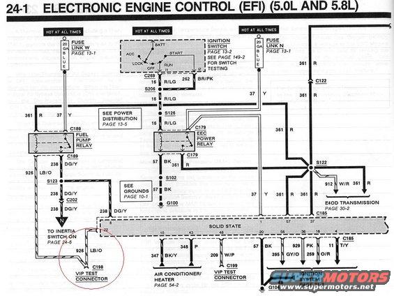
EEC/EFI wiring schematic for Ford 5.0L and 5.8L engines showing fuel pump relay, EEC power relay, inertia switch, VIP test connector and E4OD transmission feed with wire colors/codes.
Part of 1992-1996 Ford Bronco Wiring Diagrams
This is page 24-1 of a Ford factory wiring diagram set titled 'Electronic Engine Control (EFI) (5.0L and 5.8L)'. It shows the power and ground circuits for the EEC (electronic engine control) module. Power comes from two 'hot at all times' 20-gauge blue fuse links (W and N, page 13-1) and from the ignition switch (page 13-2). The diagram traces circuit 16 (R/LG) through splices S206 and S126 to connector C179 feeding both the Fuel Pump Relay and the EEC Power Relay. Fuel pump output is circuit 238 (DG/Y) routed through S123 and C202 to the inertia switch (page 24-6), with circuit 926 (LB/O) going to the C198 VIP Test Connector, which is circled in red by the uploader. Circuit 361 (R) and 37 (Y) feed multiple points including splice S122, the E4OD transmission (page 30-2), and C122. Grounds run through circuit 57 (BK) via S102 to G100 and G104. The 'Solid State' EEC module block shows pin numbers 8, 22, 10, 43, 48, 20, 60, 56, 36, 16, 4, 1, 57 and 37 with wires to the A/C-heater system (page 54-2), a second VIP test connector (C199, circuit 209 W/P), and the ignition system (page 21-2). Cross-references to power distribution (page 13-5) and grounds (page 10-1) are included.
Is this accurate? Sign in to help verify it.
Frequently asked questions
- Where does the EEC power relay get its power on the 5.0L/5.8L EFI system?
- From the ignition switch and hot-at-all-times fuse links via circuit 16 (R/LG), which runs through connector C269, splices S206 and S126, and connector C179 to the EEC Power Relay. Fuse Link W and Fuse Link N are 20 GA blue fuse links, shown on page 13-1.
- What wire color and circuit number feed the fuel pump from the fuel pump relay?
- Circuit 238, dark green/yellow (DG/Y), which runs from the fuel pump relay through C189, splice S123, and C202 to the inertia switch (see page 24-6).
- What is the VIP test connector wire for the fuel pump circuit?
- Circuit 926, light blue/orange (LB/O), which goes to connector C198, the VIP Test Connector (circled on this diagram). A second VIP Test Connector, C199, connects via circuit 209 (W/P) from EEC pin 48.
- Where do the EEC grounds go?
- Ground circuit 57 (BK) runs from the EEC Power Relay through splice S102 to ground G100 (see Grounds, page 10-1), and pin 20 of the EEC module grounds via circuit 57 (BK) to G104.
- Which EEC module pins connect to the ignition system?
- Pins 56, 36, 16 and 4 route through circuits 395 GY/O, 929 (GY/O/PK), 259 O/R and 48 to the Ignition System, shown on page 21-2. Pin 4 also carries circuit 11 T/Y to C185.
Comments
More from this build





No comments yet.