Ford E4OD & AODE/4R70W Transmission Connector Pinout - MLPS Wiring Diagram

Reference · 1992-1996 BroncoAll 411 wiring diagrams
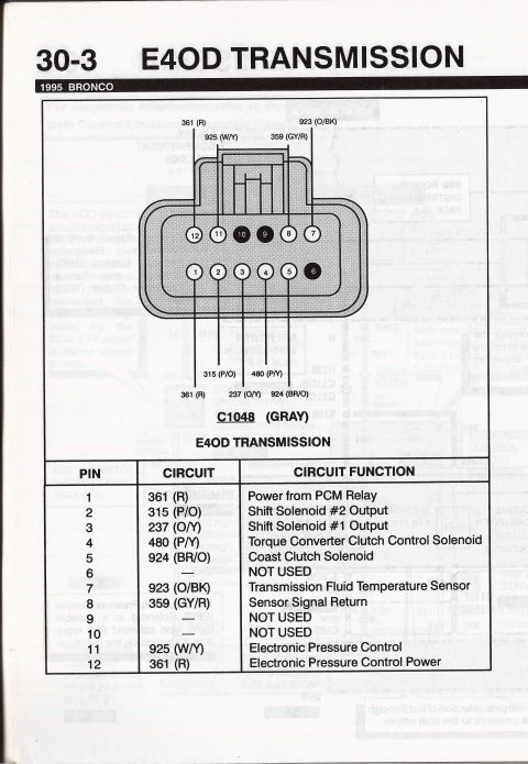
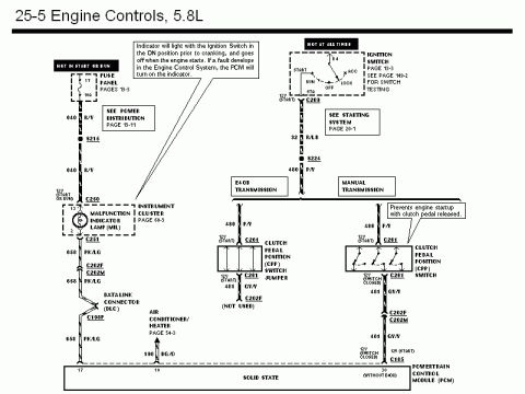
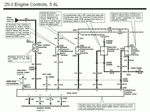
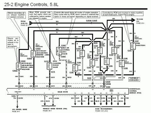
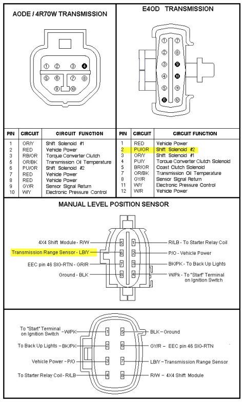


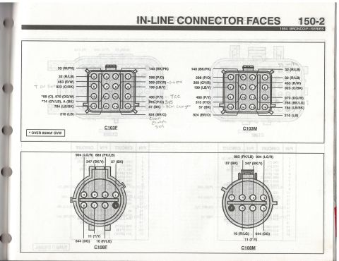
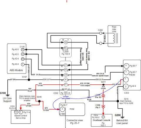





Transmission connector pinout charts: AODE/4R70W and E4OD solenoid connectors plus Manual Lever Position (TR) sensor wiring with circuit numbers and wire colors.
Part of 1992-1996 Ford Bronco Wiring Diagrams
This document is a transmission wiring/connector pinout reference showing three related diagrams. The top section compares the AODE/4R70W transmission connector (10-pin) with the E4OD transmission connector (12-pin), each with a table listing pin numbers, wire circuit color codes, and circuit functions. Functions covered include shift solenoids #1 and #2, torque converter clutch (and coast clutch solenoid on the E4OD), transmission oil temperature sensor, sensor signal return, electronic pressure control, and vehicle power feeds. The E4OD row for pin 2 (PU/OR, Shift Solenoid #2) is highlighted. The middle section shows the Manual Level (Lever) Position Sensor 8-pin connector with wire colors and destinations: 4X4 shift module (R/W), transmission range sensor (LB/Y, highlighted), EEC pin 46 signal return (GR/R), ground (BLK), starter relay coil (R/LB), vehicle power (P/O), back-up lights (BK/PK), and the ignition switch "Start" terminal (W/PK). The bottom section shows the mating side of the same 8-pin connector with the same circuits mirrored. A reader can identify each pin, its wire color, and its function for diagnosing or repairing E4OD/AODE transmission wiring and the MLPS harness.
Is this accurate? Sign in to help verify it.
Frequently asked questions
- What wire color is Shift Solenoid #2 on the E4OD transmission connector?
- Pin 2, wire color PU/OR (purple/orange), is Shift Solenoid #2 on the E4OD connector.
- Which pins are vehicle power on the E4OD connector?
- Pin 1 (RED) and pin 12 (W/R) are Vehicle Power on the E4OD connector.
- What is the wire color for the Transmission Range Sensor on the Manual Lever Position Sensor connector?
- The Transmission Range Sensor wire is LB/Y (light blue/yellow), shown on pin 6 of the sensor side and pin 7 of the mating connector.
- What does pin 5 do on the E4OD transmission connector?
- Pin 5, wire color BR/OR, is the Coast Clutch Solenoid, a circuit the AODE/4R70W connector does not have.
- Where does the W/PK wire on the MLPS connector go?
- The W/PK (white/pink) wire goes to the "Start" terminal on the ignition switch.






No comments yet.