Ford E4OD Transmission Connector Pinout Diagram - Pin & Wire Color Chart

Reference · 1987-1991 BroncoAll 175 wiring diagrams
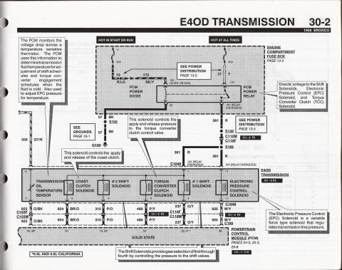
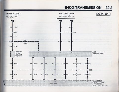
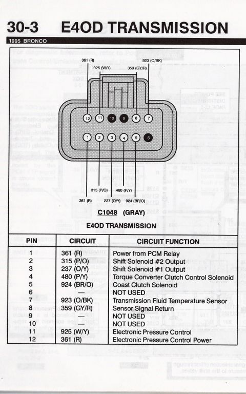
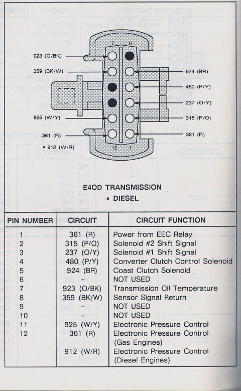









E4OD transmission connector pinout for diesel applications: 12-pin chart with shift solenoids, TCC, coast clutch, oil temp sensor, and separate EPC circuits for gas (925 W/Y) and diesel (912 W/R).
Part of 1987-1991 Ford Bronco Wiring Diagrams
This document is a pinout diagram and legend for the E4OD automatic transmission 12-pin harness connector, uploaded to a 1990 Ford Bronco gallery. The top portion shows a drawing of the connector face with pin positions numbered (7 and 6 at the top, 12 and 1 at the bottom) and wire circuit numbers with color codes called out on both sides: 923 (O/BK), 359 (BK/W), 925 (W/Y), 361 (R), and 912 (W/R, marked with a star for diesel) on the left; 924 (BR), 480 (P/Y), 237 (O/Y), 315 (P/O), and 361 (R) on the right. Below the diagram, a table lists each pin's circuit and function: pin 1 is power from the EEC relay, pins 2 and 3 are shift solenoid signals, pin 4 is the converter clutch control solenoid, pin 5 the coast clutch solenoid, pin 7 transmission oil temperature, pin 8 sensor signal return, pin 11 electronic pressure control, and pin 12 electronic pressure control (circuit 361 on gas engines, 912 on diesel engines). Pins 6, 9, and 10 are not used. This reference is useful for diagnosing E4OD wiring, solenoid, and EPC circuit problems at the transmission connector.
Is this accurate? Sign in to help verify it.
Frequently asked questions
- What is the pinout of the Ford E4OD transmission connector?
- Pin 1: 361 (R) Power from EEC Relay; Pin 2: 315 (P/O) Solenoid #2 Shift Signal; Pin 3: 237 (O/Y) Solenoid #1 Shift Signal; Pin 4: 480 (P/Y) Converter Clutch Control Solenoid; Pin 5: 924 (BR) Coast Clutch Solenoid; Pin 7: 923 (O/BK) Transmission Oil Temperature; Pin 8: 359 (BK/W) Sensor Signal Return; Pin 11: 925 (W/Y) Electronic Pressure Control; Pin 12: Electronic Pressure Control. Pins 6, 9, and 10 are not used.
- Which E4OD connector pins are not used?
- Pins 6, 9, and 10 are marked NOT USED.
- What wire is the Electronic Pressure Control (EPC) circuit on the E4OD?
- Pin 11 is circuit 925 (W/Y). Pin 12 is also Electronic Pressure Control: circuit 361 (R) on gas engines and circuit 912 (W/R) on diesel engines.
- What color wire is the E4OD transmission oil temperature sensor?
- Pin 7, circuit 923, wire color O/BK (orange/black), labeled Transmission Oil Temperature.
- Which pin controls the E4OD torque converter clutch solenoid?
- Pin 4, circuit 480 (P/Y), is the Converter Clutch Control Solenoid.






No comments yet.