1990 Ford Bronco E4OD Transmission Wiring Schematic - EEC Pins & Wire Colors
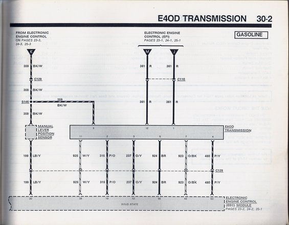
E4OD transmission wiring diagram (30-2, gasoline) showing EEC module connections, manual lever position sensor, and color-coded solenoid circuits.
This is a scanned factory wiring schematic page (30-2) for the Ford E4OD electronically controlled automatic transmission on gasoline engines, uploaded as applying to a 1990 Ford Bronco. The diagram shows the circuit path from the Electronic Engine Control system (referenced on pages 23-1/23-3, 24-1/24-3, 25-1/25-3) through connectors K, M, and J to the Manual Lever Position Sensor and the E4OD transmission connector. Key circuits shown include 359 BK/W (power feed through connector C129 and splice S146 to the MLPS and transmission pin 8) and 361 R (feeds through C110 to transmission pins 12 and 1). The lower half maps each transmission connector pin through inline connector C129 to the Electronic Engine Control (EEC) module: circuit 199 LB/Y to pin 30, 925 W/Y to pin 38, 315 P/O to pin 19, 237 O/Y to pin 52, 924 BR to pin 55, 923 O/BK to pin 42, and 480 P/Y to pin 53. Mirrored bleed-through from the reverse page shows a component location table and a 'How the Circuit Works' description. Readers can use this page to trace E4OD solenoid and MLPS wiring, wire colors, circuit numbers, and EEC pin assignments.
Is this accurate? Sign in to help verify it.
Frequently asked questions
- What circuit powers the E4OD transmission and MLPS in this diagram?
- Circuit 359 (BK/W wire) comes from the Electronic Engine Control system through connector C129 and splice S146, feeding the Manual Lever Position Sensor and E4OD transmission pin 8. Circuit 361 (R wire) feeds transmission pins 12 and 1 through connectors M, J, and C110.
- Which EEC module pins connect to the E4OD transmission?
- The diagram shows EEC module pins 30 (circuit 199 LB/Y), 38 (925 W/Y), 19 (315 P/O), 52 (237 O/Y), 55 (924 BR), 42 (923 O/BK), and 53 (480 P/Y).
- What connector sits between the E4OD transmission and the EEC module wiring?
- Inline connector C129 is shown in the harness between the transmission/MLPS circuits and the EEC module; connector C110 is shown on the 361 R circuit.
- What wire colors are used at the E4OD transmission connector?
- The transmission connector circuits shown are 361 R (pins 12 and 1), 359 BK/W (pin 8), plus 925 W/Y (pin 2), 315 P/O (pin 3), 237 O/Y (pin 5), 924 BR (pin 7), 480 P/Y (pin 4), and 199 LB/Y from the MLPS/pin 11 side.
- Does this schematic apply to diesel engines?
- The page is labeled 'GASOLINE,' so this version of the E4OD schematic is for gasoline-engine applications.
Comments
More from this build














No comments yet.