1995 Ford Bronco C103 In-Line Connector Pinout - Wire Colors & Circuits (150-2)
Reference · 1992-1996 BroncoAll 411 wiring diagrams


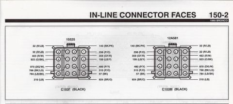

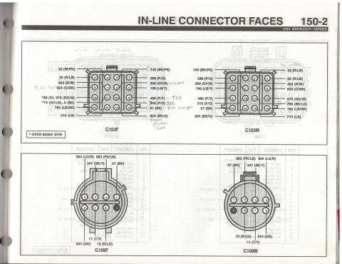
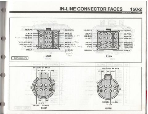




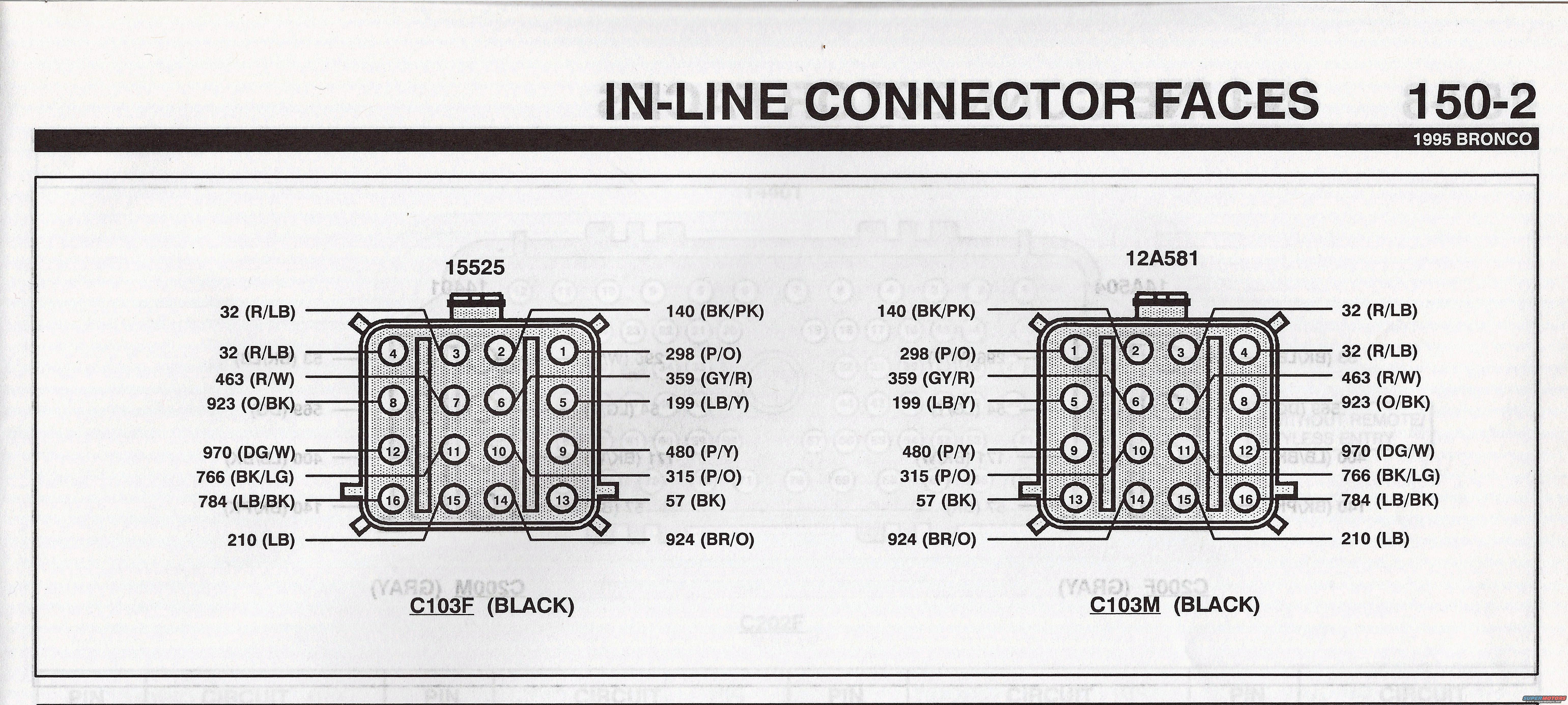
In-line connector face diagram for a 1995 Bronco showing the C103F and C103M connector cavities with wire color and circuit codes.
Part of 1992-1996 Ford Bronco Wiring Diagrams
This is page 150-2, "In-Line Connector Faces," from the 1995 Ford Bronco electrical/vacuum troubleshooting manual (EVTM). It shows face views of a mating pair of 16-pin in-line connectors: C103F (female, black, harness 15525) and C103M (male, black, harness 12A581). Each connector face is drawn with all 16 cavity positions numbered, and callout lines identify the Ford circuit number and wire color code at each cavity. Circuits shown include 32 (R/LB) at two cavities, 463 (R/W), 923 (O/BK), 970 (DG/W), 766 (BK/LG), 784 (LB/BK), 210 (LB), 140 (BK/PK), 298 (P/O), 359 (GY/R), 199 (LB/Y), 480 (P/Y), 315 (P/O), 57 (BK, ground), and 924 (BR/O). The male and female views are mirror images of each other so the same circuit lands in the mating cavity. A reader can use this page to identify a wire by circuit number and color at any pin of the C103 connector when diagnosing or repairing the engine/body harness junction on a 1995 Bronco. Faint bleed-through of the reverse page (C200/C202 connectors) is visible but not fully legible.
Is this accurate? Sign in to help verify it.
Frequently asked questions
- What connectors are shown on page 150-2 of the 1995 Bronco manual?
- The mating pair C103F (black, associated with 15525) and C103M (black, associated with 12A581), each a 16-cavity in-line connector shown face-on with circuit numbers and wire colors.
- What wire color is circuit 57 in the C103 connector?
- Circuit 57 is BK (black), located at pin/cavity 13 area of the connector face.
- Which circuits use red/light blue (R/LB) wires in connector C103?
- Circuit 32 (R/LB) appears twice on both C103F and C103M, at the two top cavities on one side of the connector.
- What circuit and color is at the pin labeled 970?
- Circuit 970 uses a DG/W (dark green/white) wire, shown at cavity 12 on both C103F and C103M.
- Are C103F and C103M pinouts the same?
- Yes: they carry the same circuits (140 BK/PK, 298 P/O, 359 GY/R, 199 LB/Y, 480 P/Y, 315 P/O, 57 BK, 924 BR/O, 32 R/LB x2, 463 R/W, 923 O/BK, 970 DG/W, 766 BK/LG, 784 LB/BK, 210 LB), drawn as mirror images since the faces mate together.





No comments yet.