Home/
Registry/
Ford/
Bronco/
1992-1996/
“pukin' dogII”/
Photo
supermotors.net/registry/media/877790
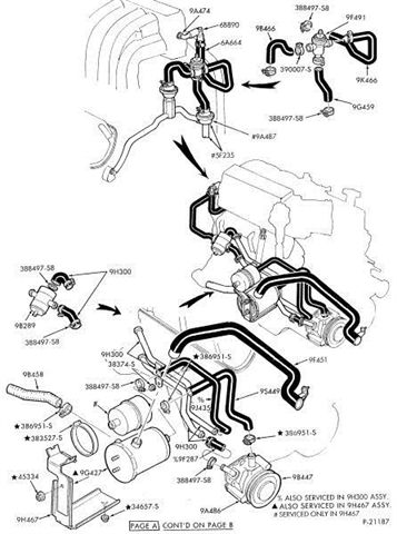
1996 Ford Bronco Secondary Air Injection (Thermactor) System Parts Diagram

Reference · 1992-1996 BroncoAll 40 vacuum routing diagrams


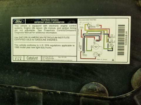
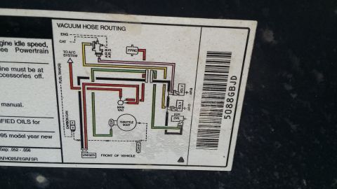
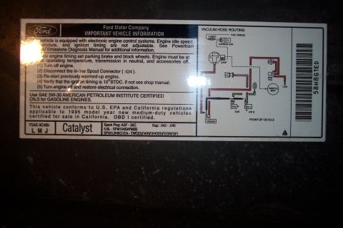
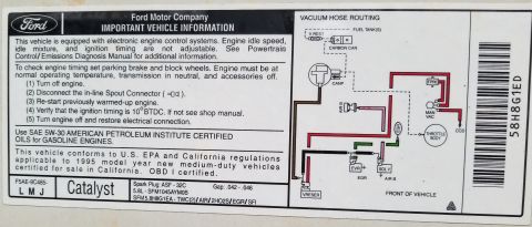
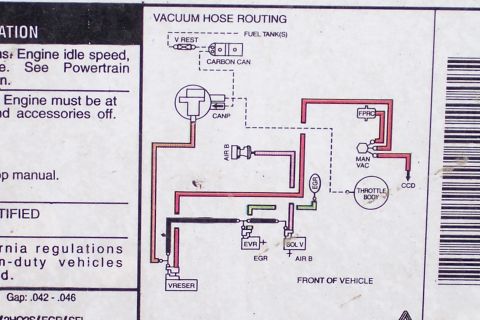
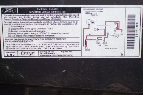








Vacuum hose routing diagram showing engine vacuum lines, connectors and Ford part numbers.
Part of 1992-1996 Ford Bronco Vacuum Routing Diagrams
This is a scanned exploded-view parts illustration of the secondary air injection (Thermactor/air pump emission) system components and hose routing on a Ford V8 engine, filed by the uploader for a 1996 Ford Bronco. The drawing shows the belt-driven air pump (9A486/9A447 area) at the lower right, the air bypass/diverter valves (9B289, 9F491), check valves, air supply tubes and hoses routed across the intake manifold and exhaust manifolds, plus a canister/filter assembly (9H438 hose, 9H467 assembly). Numerous Ford base part number callouts are given, including 9A474, 68B90, 6A664, 9A466, 9K466, 9G459, 9A487, 5F235, 9H300, 9J433, 9F451, 95449, 9F287, and hardware such as clamp/screw part numbers 388497-S8, 390007-S, 38374-S, 386951-S, 383527-S, 45334, 34657-S, and 9G427. Footnote symbols indicate which small parts are also serviced within the 9H300 or 9H467 assemblies, or serviced only in 9H467. The sheet is marked "Page A, cont'd on Page B" and carries drawing number P-21187, indicating it is the first page of a two-page parts breakdown. Readers can use it to identify air injection system component locations, hose routing, and Ford base part numbers for ordering replacements.
Is this accurate? Sign in to help verify it.
Frequently asked questions
- What does this diagram show?
- It is an exploded parts illustration of the air injection (air pump/Thermactor emission) system on a Ford V8 engine, showing the air pump, bypass/diverter valves, check valves, hoses, tubes, and mounting hardware with Ford base part number callouts.
- What part numbers are identified for the air injection hardware?
- Callouts include 9A474, 68B90, 6A664, 9A466, 9F491, 9K466, 9G459, 9A487, 5F235, 9H300, 9B289, 9J433, 9F451, 95449, 9F287, 9H438, 9H467, 9G427, 9A486 and 9A447, plus fasteners/clamps 388497-S8, 390007-S, 38374-S, 386951-S, 383527-S, 45334 and 34657-S.
- What do the triangle, dot, and star symbols mean on the diagram?
- Per the footnotes: ▲ parts are also serviced in the 9H300 assembly, ● parts are also serviced in the 9H467 assembly, and ★ parts are serviced only in 9H467.
- Is this the complete diagram?
- No. The sheet is labeled 'Page A: Cont'd on Page B,' so the parts breakdown continues on a second page.
- What drawing number does this document carry?
- The illustration is identified as P-21187.






No comments yet.