Home/
Registry/
Ford/
Bronco/
1992-1996/
“pukin' dogII”/
Photo
supermotors.net/registry/media/877789
Ford Bronco Anti-Theft Module Wiring Pinout - C237 & C238 Connector Diagram

Reference · 1992-1996 BroncoAll 411 wiring diagrams
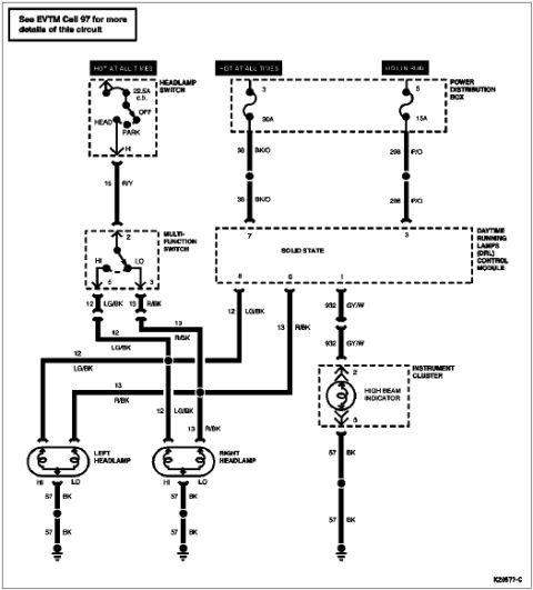
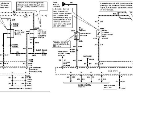
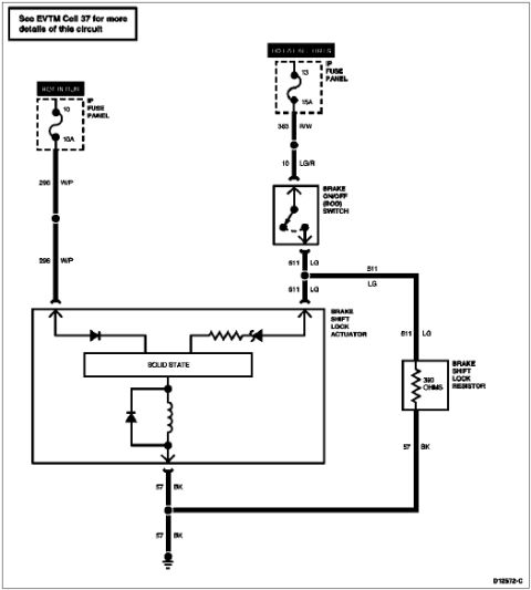
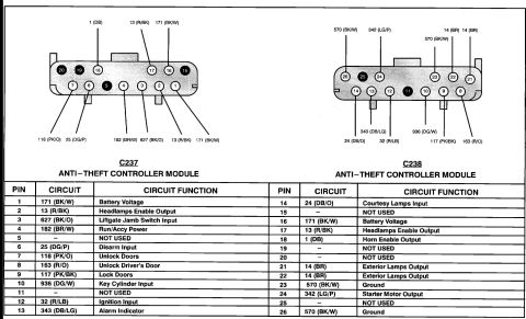













Connector pinout wiring chart for the anti-theft controller module listing pin, circuit and function with color codes.
Part of 1992-1996 Ford Bronco Wiring Diagrams
This document is a connector pinout reference for the Ford anti-theft controller module, showing two module connectors, C237 and C238. Each connector is illustrated with numbered pin cavities and callout labels identifying the circuit number and wire color at each pin. Two tables list all 26 pins with their circuit designations and functions. Connector C237 covers pins 1-13, including 171 (BK/W) Battery Voltage, 13 (R/BK) Headlamps Enable Output, 627 (BK/O) Liftgate Jamb Switch Input, 182 (BR/W) Run/Accy Power, 25 (DG/P) Disarm Input, 118 (PK/O) Unlock Doors, 163 (R/O) Unlock Driver's Door, 117 (PK/BK) Lock Doors, 936 (DG/W) Key Cylinder Input, 32 (R/LB) Ignition Input, and 343 (DB/LG) Alarm Indicator. Connector C238 covers pins 14-26, including 24 (DB/O) Courtesy Lamps Input, 1 (DB) Horn Enable Output, 14 (BR) Exterior Lamps Output (pins 21 and 22), 570 (BK/W) Ground (pins 23 and 26), and 342 (LG/P) Starter Motor Output. Several pins (5, 11, 15, 19, 20, 25) are marked NOT USED. A reader can use this to identify wire colors and functions when diagnosing or wiring the factory anti-theft system on a Ford Bronco of this era.
Is this accurate? Sign in to help verify it.
Frequently asked questions
- What are the connector numbers for the Ford Bronco anti-theft controller module?
- The anti-theft controller module uses connectors C237 (pins 1-13) and C238 (pins 14-26).
- Which wire is battery voltage on the anti-theft module?
- Circuit 171 (BK/W) provides battery voltage on both pin 1 (C237) and pin 16 (C238).
- Which pins on the anti-theft module are grounds?
- Pins 23 and 26, both circuit 570 (BK/W), are grounds on connector C238.
- What wire controls the alarm indicator?
- Pin 13, circuit 343 (DB/LG), is the Alarm Indicator.
- Which pins are not used on the anti-theft controller module?
- Pins 5, 11, 15, 19, 20, and 25 are marked NOT USED.
- What circuit handles the starter motor output?
- Pin 24, circuit 342 (LG/P), is the Starter Motor Output on connector C238.






No comments yet.