Home/
Registry/
Ford/
Bronco/
1992-1996/
“pukin' dogII”/
Photo
supermotors.net/registry/media/877830
5.0L Secondary Air System Diagram - AIR Pump, Bypass/Diverter Valve Locations

Reference · 1992-1996 BroncoAll 40 vacuum routing diagrams
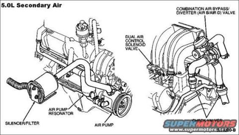
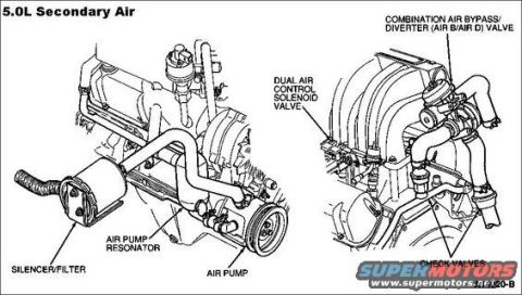
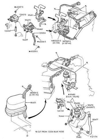

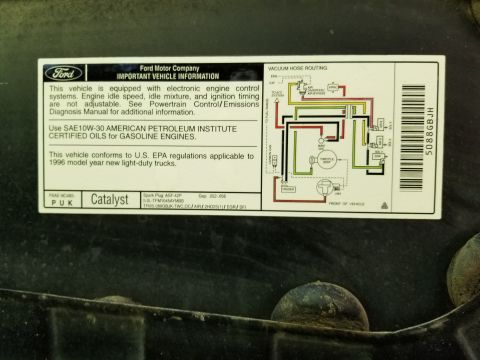
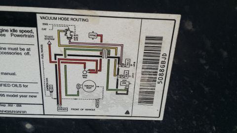
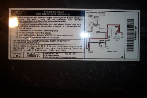
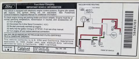
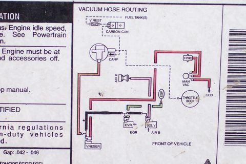
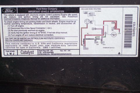
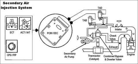

5.0L secondary air injection routing diagram labeling the air pump, silencer/filter, dual air control solenoid and air bypass/diverter valve.
Part of 1992-1996 Ford Bronco Vacuum Routing Diagrams
This document is a labeled component-location diagram for the secondary air injection (AIR) system on a 5.0L engine, titled "5.0L Secondary Air." It consists of two engine illustrations. The left illustration shows the belt-driven side of the engine and identifies the silencer/filter, the air pump resonator, and the air pump itself, mounted low on the front of the engine. The right illustration shows the upper intake manifold area and identifies the dual air control solenoid valve (mounted near the intake), the combination air bypass/diverter (AIR B/AIR D) valve located at the rear/top of the engine with its associated hoses, and the check valves in the air injection plumbing. A reader can use this diagram to locate each major secondary air component on the 5.0L engine when diagnosing emissions or air-injection problems, or when replacing the AIR bypass/diverter valve, solenoid, pump, or check valves. The diagram contains no part numbers, torque specifications, vacuum hose color codes, or explicit model-year information; it is purely a component identification/location reference. A partially visible figure reference code ending in "120-B" appears at the right edge of the page.
Is this accurate? Sign in to help verify it.
Frequently asked questions
- What components are shown in the 5.0L secondary air diagram?
- The diagram labels the silencer/filter, air pump resonator, air pump, dual air control solenoid valve, combination air bypass/diverter (AIR B/AIR D) valve, and check valves.
- Where is the combination air bypass/diverter valve located on the 5.0L engine?
- Per the diagram, the combination AIR B/AIR D valve is mounted at the upper rear area of the engine near the intake manifold, with hoses running to the check valves below.
- Where is the air pump on the 5.0L engine?
- The air pump is shown mounted low at the front of the engine on the accessory drive, with an air pump resonator and a silencer/filter connected to it.
- What is the dual air control solenoid valve shown in this diagram?
- It is labeled as a component mounted near the intake manifold that is part of the secondary air system, positioned near the combination air bypass/diverter valve.
- Does this diagram show check valves for the secondary air system?
- Yes, check valves are called out at the lower right of the second illustration, in the air injection plumbing on the engine.






No comments yet.