Home/
Registry/
Ford/
Bronco/
1992-1996/
“pukin' dogII”/
Photo
supermotors.net/registry/media/877792
1996 Ford Bronco Brake Shift Interlock Wiring Diagram - BOO Switch & Actuator

Reference · 1992-1996 BroncoAll 411 wiring diagrams
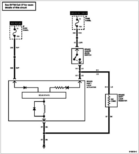
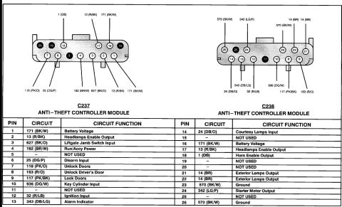
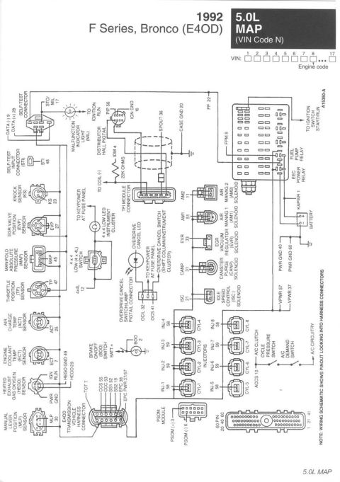
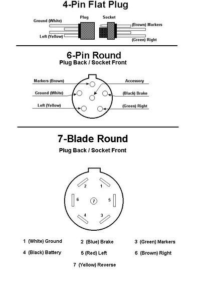
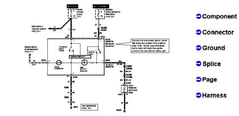













Electrical wiring diagram of the brake shift lock circuit with fuse panel feeds, BOO switch, actuator and resistor.
Part of 1992-1996 Ford Bronco Wiring Diagrams
This document is a Ford wiring diagram (diagram number D12572-C) for the brake shift interlock circuit, uploaded as applying to a 1996 Ford Bronco. It shows two power feeds from the instrument panel (I/P) fuse panel: Fuse 10 (10A, hot in RUN) supplying circuit 296 (White/Purple) directly to the Brake Shift Lock Actuator, and Fuse 13 (15A, hot at all times) supplying circuit 383 (Red/White) then circuit 10 (Light Green/Red) to the Brake On/Off (BOO) Switch. From the BOO switch, circuit 511 (Light Green) branches to both the Brake Shift Lock Actuator and a 390-ohm Brake Shift Lock Resistor. The actuator is drawn with an internal solid-state module, diodes, a resistor, and a solenoid coil. Both the actuator and resistor ground through circuit 57 (Black) wires that join at a splice before reaching chassis ground. A callout notes to see EVTM Cell 37 for more details of this circuit. A reader can learn the fuse locations and ratings, wire circuit numbers and color codes, component names, resistor value, and ground path for diagnosing brake shift interlock problems (e.g., a shifter that will not come out of Park).
Is this accurate? Sign in to help verify it.
Frequently asked questions
- Which fuses power the brake shift interlock circuit?
- Two I/P fuse panel fuses: Fuse 10 (10A, hot in RUN) feeds the Brake Shift Lock Actuator via circuit 296 W/P, and Fuse 13 (15A, hot at all times) feeds the Brake On/Off (BOO) Switch via circuits 383 R/W and 10 LG/R.
- What wire color runs from the brake switch to the brake shift lock actuator?
- Circuit 511 LG (Light Green) runs from the Brake On/Off (BOO) Switch to the Brake Shift Lock Actuator, and also to the Brake Shift Lock Resistor.
- What is the value of the brake shift lock resistor?
- The Brake Shift Lock Resistor is shown as 390 ohms.
- How is the brake shift lock actuator grounded?
- Both the actuator and the resistor ground through circuit 57 BK (Black) wires that join at a splice before going to chassis ground.
- Where can more details on this circuit be found?
- The diagram states: 'See EVTM Cell 37 for more details of this circuit.'






No comments yet.