Home/
Registry/
Ford/
Bronco/
1992-1996/
“pukin' dogII”/
Photo
supermotors.net/registry/media/877813
1996 Ford Bronco F-150 4x4 Locking Hub & Front Spindle Exploded Diagram

Reference · 1992-1996 BroncoAll 169 exploded parts diagrams
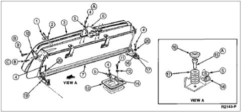
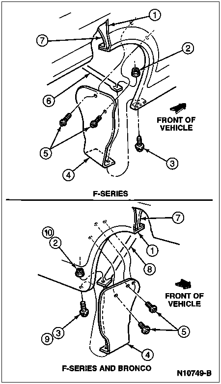
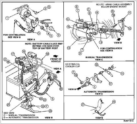
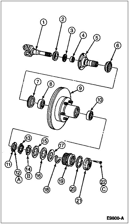












Exploded parts breakdown of a front wheel hub, brake rotor, spindle, bearings and seals with numbered callouts.
Part of 1992-1996 Ford Bronco Exploded Parts Diagrams
This document is an exploded parts diagram (figure identifier E9800-A) showing the front hub, rotor, spindle, and automatic/manual locking hub assembly for a four-wheel-drive front axle, uploaded as applying to a 1996 Ford Bronco/F-150. The diagram depicts, in disassembly order: the axle shaft with U-joint yoke and splined stub shaft (item 1), followed by seals, a bearing/spacer, thrust washers, and the wheel spindle (items 2-6); the inner bearing seal, inner wheel bearing, the hub-and-rotor assembly with wheel studs, and the outer wheel bearing (items 7-10); and the locking hub retention components including washers, snap rings, lock rings, spring, the internal splined hub body/cam assembly, and the hub cap/dial with retaining screw (items 11-22). Three lettered sub-callouts (A, B, C) accompany items 12, 14, and 22. The scan contains no text legend or parts table on this page, so component names, part numbers, and torque values are not identified here, only the numbered callout positions and their physical relationships in the exploded view. A reader can learn the assembly sequence and relative position of each component in the front hub and locking hub stack-up.
Is this accurate? Sign in to help verify it.
Frequently asked questions
- How many parts are called out in this locking hub exploded diagram?
- The diagram shows 22 numbered callouts (1 through 22), plus three lettered sub-callouts A, B, and C associated with items 12, 14, and 22.
- Does this diagram include a parts legend or part numbers?
- No. This page shows only the exploded view with numbered callouts and the figure identifier E9800-A; no legend, part names, or part numbers are printed on the scan.
- What is the figure reference number on this diagram?
- The figure identifier printed at the bottom right is E9800-A.
- What does the diagram show about assembly order?
- It shows the exploded stack-up from the axle shaft and spindle (items 1-6), through the inner seal, bearings, and hub/rotor assembly (items 7-10), to the locking hub components and cap with retaining screw (items 11-22).






No comments yet.