1990 Ford Bronco Instrument Cluster Wiring Diagram 60-1 - Gas with Tachometer
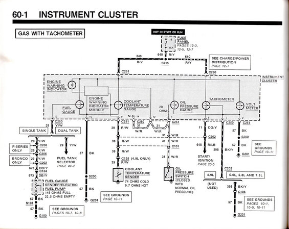
Instrument cluster wiring diagram for gas-with-tachometer clusters showing fuel, temperature, oil pressure gauges, senders and color-coded circuits.
This document is page 60-1 of a Ford factory wiring diagram set, showing the Instrument Cluster circuit for gas engines equipped with a tachometer. Power enters the cluster from fuse 18 (15A) in the fuse panel, hot in start or run, via circuit 640 R/Y through splice S215 and connectors C251 (pin 5) and C250 (pin 13). The cluster contains the engine warning indicator and module, fuel gauge, coolant temperature gauge, oil pressure gauge (with a 20-ohm resistor), tachometer, and volt meter. The fuel gauge circuit (29 Y/W) branches for single tank and dual tank configurations, with F-Series and Bronco-specific connectors (C206, C202), leading through circuit 673 DB/Y to the fuel gauge sender/electric fuel pump (145 ohms full, 22.5 ohms empty). The coolant temperature sender reads 74 ohms cold and 9.7 ohms hot on circuit 39 R/W. The oil pressure switch (closed with normal oil pressure) connects via circuit 31 W/R. The tachometer receives signal on circuit 648 R/LB from start/ignition and uses circuit 398 BK/Y for 5.0L, 5.8L and 7.5L engines (not used on 4.9L). Grounds shown include G100, G201, S103, and S200, with cross-references to grounds pages 10-1 through 10-11 and related pages 12-3/12-5/12-7, 20-5, and 49-2.
Is this accurate? Sign in to help verify it.
Frequently asked questions
- What fuse powers the instrument cluster on the gas-with-tachometer setup?
- Fuse 18, a 15A fuse in the fuse panel (pages 12-3, 12-5, 12-7), hot in start or run, feeding circuit 640 R/Y through splice S215 to connectors C251 and C250.
- What are the resistance values for the fuel gauge sender?
- The fuel gauge sender/electric fuel pump reads 145 ohms full and 22.5 ohms empty.
- What resistance should the coolant temperature sender show?
- 74 ohms cold and 9.7 ohms hot, on circuit 39 R/W.
- How does the oil pressure switch operate in this circuit?
- The oil pressure switch is closed with normal oil pressure and connects to the cluster via circuit 31 W/R through connector C101, working with a 20-ohm resistor at the oil pressure gauge.
- What wire feeds the tachometer signal?
- The tachometer connects via circuit 11 DG/Y through C202 to circuit 648 R/LB from the start/ignition system (page 20-5); its other lead uses circuit 398 BK/Y, which is not used on the 4.9L but applies to 5.0L, 5.8L and 7.5L engines.
Comments
More from this build













No comments yet.