1995 Ford Bronco 5.8L (MAP) PCM Connector C185 Pinout - 60-Pin EEC Diagram

Reference · 1987-1991 BroncoAll 175 wiring diagrams
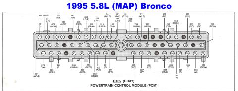
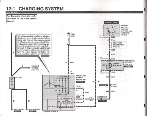
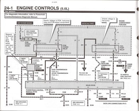
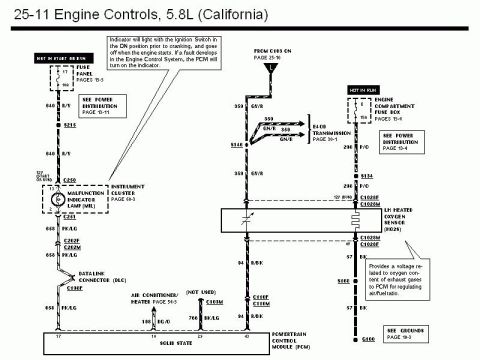
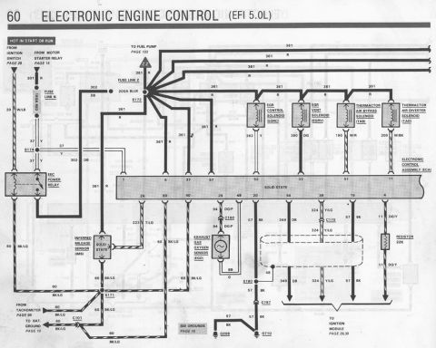



Powertrain control module C185 gray connector pin-out diagram for a 1995 5.8L Bronco showing each pin position with its wire color code.
Part of 1987-1991 Ford Bronco Wiring Diagrams
This document is a pinout diagram for connector C185, the gray 60-pin Powertrain Control Module (PCM / EEC) connector on a 1995 Ford Bronco with the 5.8L (MAP-equipped) engine. The connector face is drawn with all 60 cavities arranged in three rows (pins 1-20, 21-40, and 41-60), with some positions shown shaded (5, 13, 14, 15, 18, 24, 34, 35, 39, 44, 50, 54). Leader lines from individual pins identify the Ford circuit number and wire color code attached to each cavity, for example 37 (Y), 926 (LB/O), 361 (R), 570 (BK/W), 914 (T/O), and many others using standard abbreviations such as LG (light green), GY (gray), PK (pink), BR (brown), T (tan), O (orange), P (purple), W (white), BK (black), Y (yellow), DG (dark green), and LB (light blue). A reader can use this diagram to identify which circuit number and wire color corresponds to each PCM connector pin when diagnosing engine-control wiring, back-probing the harness, or verifying continuity on a 1995 5.8L MAP Bronco. It is one page of a larger album of 1995 Bronco EVTM wiring-diagram scans.
Is this accurate? Sign in to help verify it.
Frequently asked questions
- What connector does this diagram show?
- It shows C185, the gray 60-pin Powertrain Control Module (PCM) connector for a 1995 5.8L (MAP) Ford Bronco.
- How many pins does the 1995 Bronco PCM connector have?
- 60 pins, arranged in three rows: 1-20 on top, 21-40 in the middle, and 41-60 on the bottom.
- What wire circuit is shown for pin 1 area of the connector?
- The callout nearest pin 1 is circuit 37 with a yellow (Y) wire.
- What do the numbers and letters in the callouts mean?
- Each callout gives a Ford circuit number followed by the wire color code in parentheses, e.g. 926 (LB/O) is circuit 926 with a light blue/orange wire, 570 (BK/W) is circuit 570 with a black/white wire.
- Does this diagram apply to MAF-equipped Broncos?
- The diagram is specifically titled for the 1995 5.8L (MAP) Bronco; separate MAF-related pages exist in the same document set.






No comments yet.