Ford Bronco E4OD Transmission Cooler & Remote Filter Plumbing Diagram
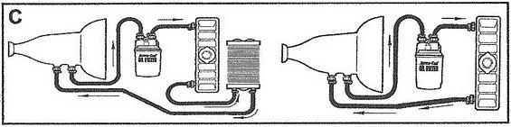
Schematic showing oil-filter and oil-cooler hose routing on an engine with directional flow arrows.
Part of 1987-1991 Ford Bronco Schematics
This document is a schematic diagram (labeled "C") illustrating two plumbing configurations for an automatic transmission fluid cooling circuit with an in-line remote spin-on transmission fluid filter (the filter canister is labeled "Perma-Cool OIL FILTER"). The left diagram shows the transmission's fluid line routed first through the remote filter, then into the radiator's in-tank cooler, then through an external auxiliary transmission cooler (stacked-plate/fin style), and finally returning to the transmission. The right diagram shows a simpler setup in which fluid passes from the transmission through the remote filter into the radiator's in-tank cooler and directly back to the transmission, without an auxiliary cooler. Directional arrows on both diagrams indicate the flow path of transmission fluid through the hoses and coolers. A reader can learn where to plumb a remote spin-on transmission filter relative to the factory radiator cooler, and how an optional auxiliary cooler is placed downstream of the radiator cooler in the return line. The document contains no written instructions, part numbers, torque specifications, model years, or vehicle identification, it is purely pictorial. It was uploaded to a 1990 Ford Bronco gallery alongside E4OD transmission-related documents, suggesting intended use for an E4OD transmission cooler/filter installation, though the diagram itself is generic.
Is this accurate? Sign in to help verify it.
Frequently asked questions
- Where does the remote transmission filter go in the cooler line?
- According to the diagram, the remote spin-on filter (labeled Perma-Cool OIL FILTER) is plumbed in-line between the transmission's fluid outlet and the radiator's in-tank cooler, so fluid passes through the filter before entering the radiator cooler.
- Where is the auxiliary transmission cooler installed relative to the radiator cooler?
- In the left diagram, the auxiliary cooler is installed downstream of the radiator in-tank cooler; fluid flows from the transmission, through the filter, through the radiator cooler, then through the auxiliary cooler before returning to the transmission.
- Can the remote filter be used without an auxiliary cooler?
- Yes. The right diagram shows a configuration with only the remote filter and the radiator in-tank cooler, with fluid returning directly from the radiator to the transmission.
- Does the diagram show fluid flow direction?
- Yes, arrows along the hose lines in both diagrams indicate the direction of transmission fluid flow through the filter and coolers.
Comments
More from this build














No comments yet.