Home/
Registry/
Ford/
Bronco/
1992-1996/
1996 Ford Bronco/
Photo
supermotors.net/registry/media/907963
Shop manual page 03-01B-64 roller and non-roller hydraulic tappe…

Reference · 1992-1996 BroncoAll 142 service procedures

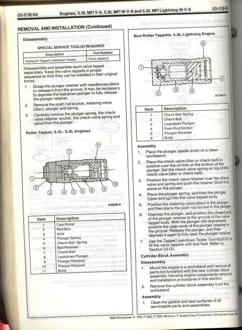
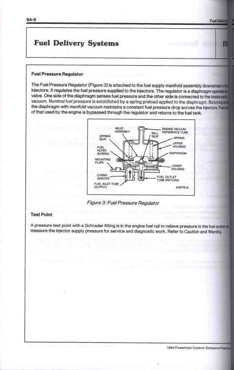
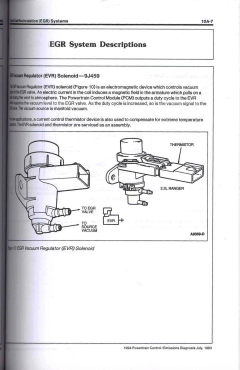
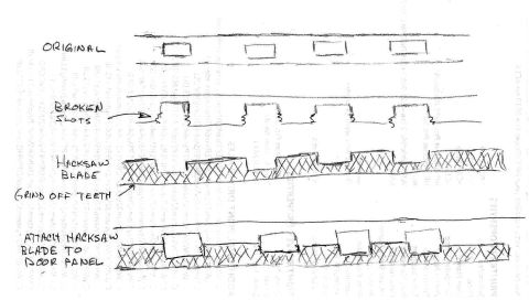
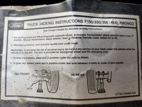


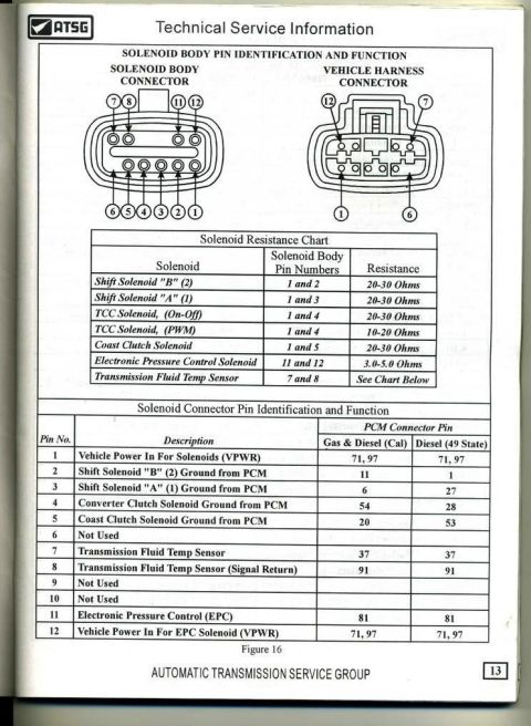



Service manual page 03-01B-64 on tappet disassembly and assembly for 5.0L/5.8L roller and 5.8L Lightning non-roller tappets, with Leakdown Tester TOOL-6500-E.
Part of 1992-1996 Ford Bronco Service Procedures
rf 5.0L MFI V-B, 5.8L MFI W-V-8 and 5.8L MFI Lightning W-V-8 03-0 I. 1 03-01 B64 Engines, REMOVAL AND INSTALLATION (Continued) Non-Roller Tappets, 5.8L Lightning Engine Disassembly SPECIAL SERVICE TOOL(S) REQUIRED 5 Description Tool Number Hydraulic Tappet Leakdown Tester TOOL-GSOO-E Disassemble and assemble each valve tappet G) ' separately. Keep the valve tappets in proper " sequence so that they can be installed in their original - + bores. . . J r 1. Grasp the plunger retainer with needlenose pliers ' It). > to release it from the groove. It may be necessary 0 to depress the leakdown plunger to fully release 3 4 the plunger retainer. Mm 2. Remove the push rod socket, metering valve (disc). plunger and spring. . . 3. Carefully remove the plunger spring, the check Item Description valve retainer socket, the check valve spring and 1 Check Ball Spring valve from the plunger. 2 Check Ball 3 Leakdown Plunger Roller Tappet, 5.0L/5.8L Engines 4 Push Rod Socket 5 Plunger Retainer 6 Body 11 7 Assembly CR 1. Place the plunger upside down on a clean workbench. W 7 _ 2. Place the check valve (disc or check ball) in = position over the oil hole on the bottom of the . _ ,. plunger. Set the check valve spring on top of the 1 , ' check valve (disc or check ball). , ~. 3. Position the check valve retainer over the check 2 valve and spring and push the retainer down into 3 d1) 5 6 8 9 place on the plunger. 5 4. Place the plunger spring, and then the plunger (open end up) into the valve tappet body. 51" 5. Position the metering valve (disc) in the plunger and then place the push rod socket in the plunger; Item Description 6. Depress the plunger, and position the closed end;a of the plunger retainer in the groove of the valve 1 car" R" tappet body. With the plunger still depressed. 2 Needles position the open ends of the plunger retainer in 3 Axle the groove. Release the plunger, and then 4 Plunger Spring depress it again to fully seat the plunger retainer. 5 Cheek 5? Spring 7. Use the Tappet Leakdown Tester Tool-6500E to 6 38 Rea'ner till the valve tappets with test tluid. Refer to 7 Check Ball Section 03-00. .1 8 Leakdown Plunger . . 9 Plunge! Retainer Cylinder Block Assembly 10 Plunger Retainer Dlsassembly 1 1 Body 1. Mount the engine in a workstand and remove all parts not furnished with the new cylinder block assembly following engine components removal and installation procedures in this section. 2. Remove the cylinder block assembly from the workstand. Assembly 1. Clean the gasket and seal surfaces of all serviceable parts and assemblies. 1994 Econoline lF-150. F-250. F-350/ Bronco / F-Super Duty Powertrain / Drivetrain Au
Is this accurate? Sign in to help verify it.






No comments yet.