Home/
Registry/
Ford/
Bronco/
1978-1979/
1978 Ford Bronco/
Photo
supermotors.net/registry/media/914397
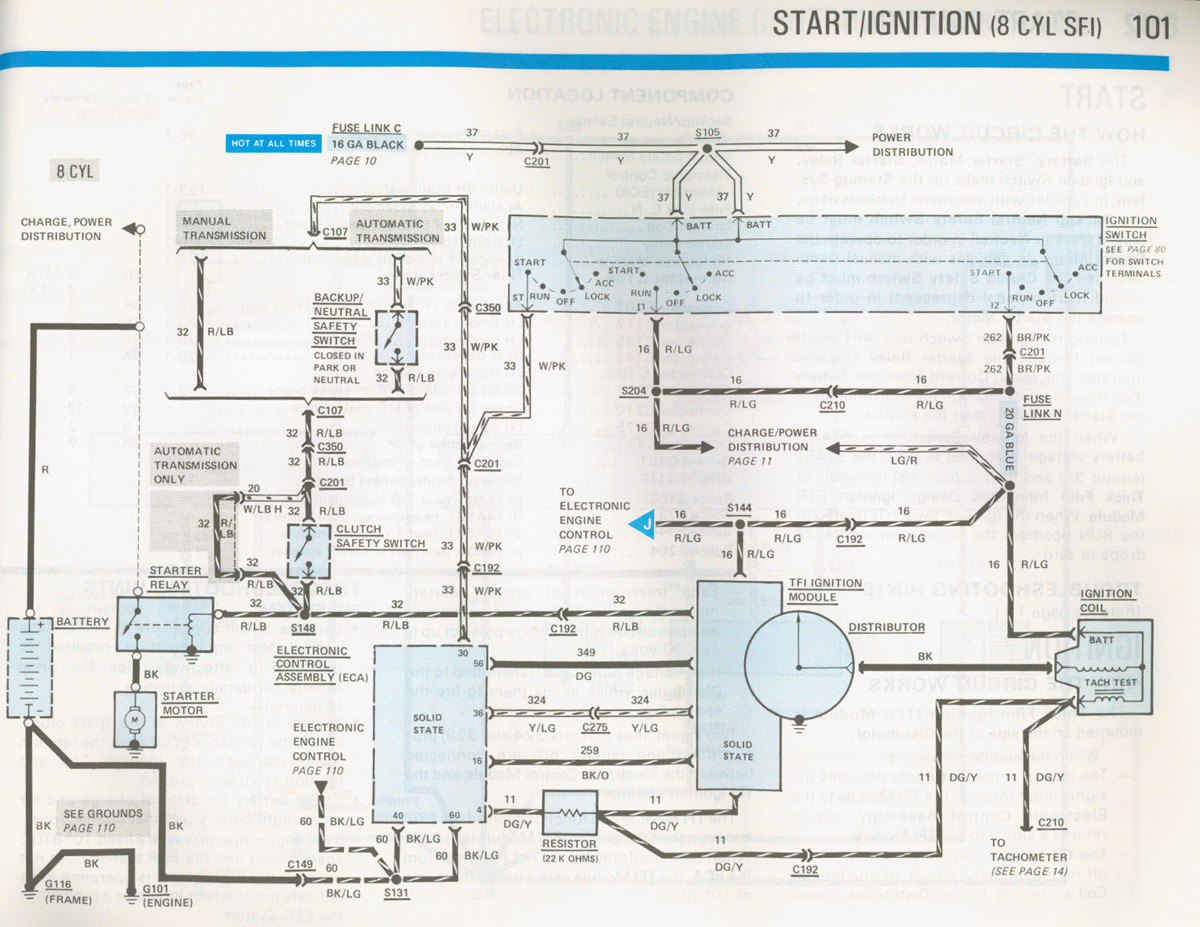
1986 Ford Mustang 5.0 V8 SFI Start/Ignition Wiring Diagram - TFI, Starter Relay
Reference · 1978-1979 BroncoAll 116 wiring diagrams
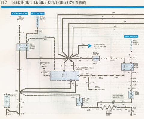
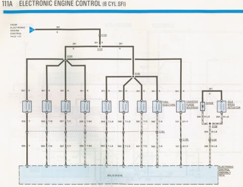
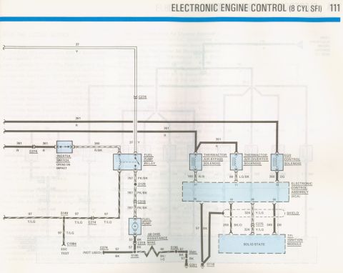
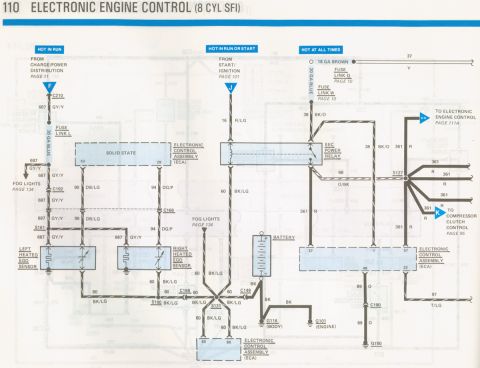
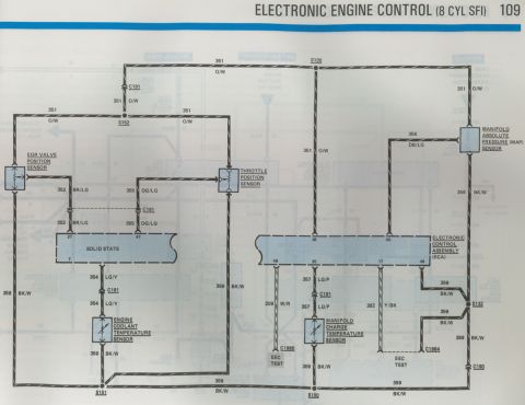
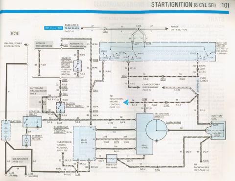
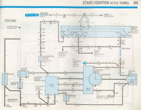


Wiring diagram of the start and ignition system for an 8-cylinder SFI, showing the ignition switch, starter relay, and electronic control assembly.
Part of 1978-1979 Ford Bronco Wiring Diagrams
This is page 101 of a Ford factory-style electrical vacuum troubleshooting manual (EVTM), showing the START/IGNITION circuit wiring diagram for the 8-cylinder SFI (sequential fuel injection) engine, filed in an album of 1986 Mustang pages. The diagram traces battery power from Fuse Link C (16 GA black, hot at all times) through splice S105 on circuit 37 (yellow) to the ignition switch BATT terminals. It shows the start circuit (32 R/LB) routed through either the backup/neutral safety switch (automatic transmission, closed in Park or Neutral) or the clutch safety switch (manual transmission) to the starter relay and starter motor. Run/start power (circuit 16 R/LG) feeds the ignition coil and the electronic engine control system, with circuit 262 BR/PK through Fuse Link N feeding charge/power distribution. The TFI ignition module on the distributor connects to the Electronic Control Assembly (ECA) via circuits 349 DG, 324 Y/LG, and 259 BK/O, with a 22K-ohm resistor in the DG/Y tach signal line to the tachometer. Grounds G101 (engine) and G116 (frame) and connectors C107, C149, C192, C201, C210, C275, C350 plus splices S105, S131, S144, S148, S204 are identified. Cross-references point to pages 10, 11, 14, 80, and 110.
This document covers 1986, which may differ from this 1978 Ford Bronco.
Is this accurate? Sign in to help verify it.
Frequently asked questions
- What fuse link powers the ignition switch on the 8-cylinder SFI start/ignition circuit?
- Fuse Link C, a 16 gauge black fuse link (hot at all times), feeds circuit 37 (yellow) through connector C201 and splice S105 to the BATT terminals of the ignition switch. Fuse Link N (20 GA blue) is also shown on circuit 262 BR/PK.
- What wire color is the start circuit to the starter relay?
- Circuit 32, red/light blue (R/LB), runs from the ignition switch through the backup/neutral safety switch (automatic) or clutch safety switch (manual) to the starter relay.
- What is the resistor value in the tachometer signal circuit?
- A 22 K ohm resistor is shown in the 11 DG/Y (dark green/yellow) circuit between the TFI ignition module wiring and the tachometer (see page 14).
- When is the backup/neutral safety switch closed?
- The diagram notes the backup/neutral safety switch is closed in Park or Neutral (automatic transmission).
- What circuits connect the TFI ignition module to the ECA?
- Circuits shown include 349 DG (pins 30/56), 324 Y/LG through C275 (pin 36), 259 BK/O (pin 16), and 11 DG/Y (pin 4); grounds run on 60 BK/LG through C149 and S131.






No comments yet.