Home/
Registry/
Ford/
Bronco/
1978-1979/
1978 Ford Bronco/
Photo
supermotors.net/registry/media/914400
1986 Ford Mustang 5.0L EEC-IV Wiring Diagram - Fuel Pump & EGR (8 Cyl SFI)
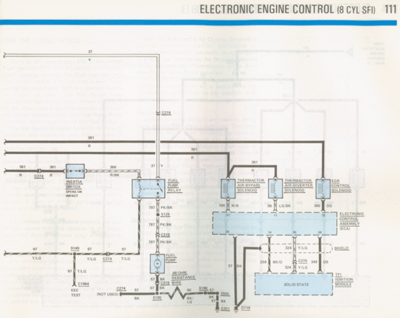
Wiring diagram of electronic engine control for an 8-cylinder SFI, showing the inertia switch, fuel pump relay, thermactor solenoids, and ignition module.
This page (numbered 111) is a factory-style wiring diagram titled "Electronic Engine Control (8 CYL SFI)" covering the EEC-IV Sequential Fuel Injection system on a 5.0L V8. The "How The Circuit Works" text explains (where legible) that fuel is injected sequentially by fuel injectors, pressure is supplied by an electric fuel pump, and the fuel pump relay is energized by the Electronic Control Assembly (ECA) with the inertia switch closed. The diagram traces the fuel pump feed: circuit 37 (Yellow) and circuit 361 (Red) through connector C274 and the inertia switch (opens on impact, circuit 366 R/BK) to the fuel pump relay, then circuit 787 (PK/BK) through splice S129 and connector C319 to the fuel pump. It also shows the Thermactor Air Bypass Solenoid (circuit 100 W/R to ECA pin 51), Thermactor Air Diverter Solenoid (99 LG/BK to pin 11), and EGR Control Solenoid (360 DG to pin 33). ECA lower pins connect via 324 Y/LG (shielded, through C275) and 349 DB to the TFI ignition module, plus 259 BK/O and ground circuit 57 BK to grounds G301/G118. A 68-ohm resistance wire, EEC TEST connector (via C1984, circuit 97 T/LG), and splices S149, S195, S196, S505 are shown.
Is this accurate? Sign in to help verify it.
Frequently asked questions
- What wire circuit feeds the fuel pump from the fuel pump relay?
- Circuit 787, a pink/black (PK/BK) wire, runs from the fuel pump relay through splice S129 and connector C319 to the fuel pump.
- What does the inertia switch do in this circuit?
- The inertia switch, labeled "opens on impact," is in the fuel pump relay power path (circuits 361 R and 366 R/BK through connector C274); when it opens, power to the fuel pump relay is cut.
- Which ECA pins control the thermactor and EGR solenoids?
- The Thermactor Air Bypass Solenoid connects via circuit 100 W/R to ECA pin 51, the Thermactor Air Diverter Solenoid via 99 LG/BK to pin 11, and the EGR Control Solenoid via 360 DG to pin 33.
- How does the ECA connect to the TFI ignition module?
- ECA pin 36 connects via shielded circuit 324 Y/LG through connector C275, and pin 56 connects via circuit 349 DB, to the solid-state TFI ignition module.
- Where does the fuel pump ground circuit go?
- Circuit 57 BK runs from the fuel pump through C319, past an unused C274 terminal, splice S195, a 68-ohm resistance wire (circuit 60 BK/LG), splices S196 and S505, to grounds G301 and G118.
Comments
More from this build














No comments yet.